
Advanced Composited & Plastics Education Module
This teaching module is aimed at providing a basic understanding of polymer matrix fiber reinforced composites, terminology and basic types of fibers and matrices used, advantages, applications, manufacturing techniques, sandwich, ceramic and metal matrix composites. The module is currently designed to serve the needs of senior undergraduate or fresh graduate students, entering the area of composites.
The most important of non-metallic materials are fiber composites which since their introduction have had a major impact on structures in a variety of applications including commercial and defense industries. The reason for this is that most composites offer significantly high advantages in terms of specific strength (strength – to -weight ratio) and specific stiffness (stiffness – to- weight) ratio. The other major advantage of composites is their ability to provide tailorability and directional properties.
A COMPOSITE MATERIAL can be defined as a macroscopic combination of two or more distinct materials, having a recognizable interface between them. However, because composites are usually used for their structural properties, the definition can be restricted to include only those materials that contain a reinforcement (such as fibers or particles) supported by a binder (matrix) material.
Thus, composites typically have a discontinuous fiber or particle phase or particle phase that is stiffer and stronger than the continuous matrix phase. In order to provide reinforcement, there generally must be a substantial volume fraction (10% or more) of the discontinuous phase. There are, however, exceptions that may still be considered composites, such as rubber-modified polymers, where the discontinuous phase is more compliant and more ductile than the polymer, resulting in improved toughness.
Composites can be divided into classes in various manners. One simple classification scheme is to separate them according to reinforcement forms-particulate-reinforced, fiber reinforced, or laminar composites. Fiber-reinforced composites can be further divided into those containing discontinuous or continuous fibers.
A reinforcement is considered to be a “particle” if all of its dimensions are roughly equal. Thus, particulate-reinforced composites include those reinforced by spheres, rods, flakes, and many other shapes of roughly equal axes. There are also materials, usually polymers, that contain particles that extend rather than reinforce the material. These are generally referred to as “filled” systems. Because filler particles are included for the purpose of cost reduction rather than reinforcement, these composites are not generally considered to be particulate composites. Nonetheless, in some cases, the filler will also reinforce the matrix material. The same may be true for particles added for nonstructural purposes such as fire resistance, control of shrinkage, and increased thermal conductivity.
Fiber-reinforced composites contain reinforcements having lengths much greater than their cross-sectional dimensions. Such a composite is considered to be a discontinuous fiber or short fiber composite if’ its properties vary with fiber length. On the other hand, when the length of the fiber is such that any further increase in length does not, for example, further increase the elastic modulus of the composite, the composite is considered to be continuous fiber reinforced. Most continuous fiber (or continuous filament) composites, in fact, contain fibers that are comparable in length to the overall dimensions of the composite part.
Laminar composites are those composed of two (or more) layers with two of their dimensions being much larger than their third. Complicating the definition of a composite as having both continuous and discontinuous phases is the fact that in a laminar composite, neither of these phases may be regarded as truly continuous in three dimensions.
With some few specific exceptions, only “high-performance” composites will be considered in this Volume. These are composites that have superior performance compared to conventional structural materials such as steel and aluminum alloys. Thus, the emphasis will be on continuous fiber reinforced composites, although the principles will often be applicable to other types of composites as well. Furthermore, continuous fiber reinforced composites will generally be referred to as simply fiber reinforced composites, and, in some cases, as merely fiber composites or composites. In addition, composites with organic (resin) matrices will be emphasized throughout this volume, both because such composites are the most commonly used and because of the significant dissimilarities between organic-matrix composites and those made with metal ceramic, and carbon matrices.
Composite materials were developed because no single, homogeneous structural material could be found that had all of the desired attributes for a given application. Fiber-reinforced composites were developed in response to demands of the aerospace community, which is under constant pressure for materials development in order to achieve improved performance. Aluminum alloys, which provide high strength and fairly high stiffness at low weight, have provided good performance and have been the main materials used in aircraft structures over the years. However, both corrosion and fatigue in aluminum alloys have produced problems that have been very costly to .remedy. World War 11 ‘Promoted a need for materials with improved structural properties. in response, fiber-reinforced composites were developed, and by the end of the war, fiberglass reinforced plastics had been used successfully in filament-wound rocket motors and in various other structural applications. These materials were put into broader use in the 1950s, and initially seemed to be the only viable approach available for the elimination of corrosion and crack formation in high-performance structures. Although more recent developments in metallic materials have led to some solutions to these problems, fiber-reinforced composites still provide other substantial benefits to designers and manufacturers.
Inexpensive fiberglass composites are used today in a wide variety of applications, from consumer products, such as the fiberglass boat to aerospace. More advanced fiber-reinforced composites, however, have been limited in their commercial use because of high materials cost, lack of widely distributed property and processing data bases, and the absence of rapid and efficient manufacturing techniques. However, fiber-reinforced composites have been developed and widely applied in aerospace applications to satisfy requirements for enhanced performance and reduced maintenance costs. In large commercial aircraft they have found application because of the weight considerations that were highlighted by the energy crisis of the 1970s.
Fiber composites offer many superior properties. Almost all high-strength/high-stiffness materials fail because of the propagation of flaws. A fiber of such a material is inherently stronger than the bulk form because the size of a flaw is limited by the small diameter of the fiber. In addition, if equal volumes of fibrous and bulk material are compared, it is found that even if a flaw does produce failure in a fiber, it will not propagate to fail the entire assemblage of fibers, as would happen in the bulk material. Furthermore, preferred orientation may be used (as in aramid and carbon fibers) to increase the lengthwise modulus, and perhaps strength, well above isotropic values. When this material is also lightweight, there is a tremendous potential advantage in strength-to-weight and/or stiffness-to-weight ratios over conventional materials. These desirable fiber properties can be converted to practical application when the fibers are embedded in a matrix that binds them together, transfers load to and between the fibers, and protects them from environments and handling. In addition, fiber-reinforced composites are ideally suited to anisotropic loading situations where weight is critical. The high strengths and moduli of these composites can be tailored to the high load direction(s), with little material wasted on needless reinforcement.
Glass fiber reinforced organic composites are the most familiar and widely used and have had extensive application in industrial, consumer, military, and aerospace markets. Carbon fiber reinforced resin matrix composites are by far the most commonly applied advanced (non fiberglass), composites for a number of reasons. The extremely high specific properties, high materials that are readily available, reproducible material forms, increasingly favorable cost projections, and comparative ease of manufacture. Composites reinforced with aramid other organics, and boron fibers, and with carbide, alumina, and other ceramic fibers also used. Recent technology has provided a various reinforcing fibers and matrices that combined to form composites having range of very exceptional properties. In many instances the sheer number of available material combinations can make selection of materials for evaluation a difficult and almost overwhelming task. In addition, once a material is selected, the choice of an optimal fabrication, process can be very complex.
Composite Materials can be Tailored in Different Directions


The most commonly used reinforcement material in fiber composites used in load bearing sandwich construction is the E-glass fiber. It has good mechanical properties and environmental resistance, but it’s competitiveness comes primarily from the relative low price. There are other types of glass reinforcement like S and R-glass with slightly better mechanical properties but their price are significantly higher at present time. The main ingredient in glass is Si02, about 50-70%, but other metal oxides are often added such as Al2O3, Fe2O3 and CaO. The main drawback with glass reinforcement is that the elastic modulus is low and that the density is higher than for other reinforcements. Reinforcements need not necessarily be in the form of long fibers. One can have them in the form of particles, flakes, whiskers, discontinuous fibers, continuous fibers, and sheets. It turns out that the great majority of materials are stronger and stiffer in the fibrous form than in any other form, thus the great attraction of fibrous reinforcements. Specifically, in this category, we are most interested in the advanced fibers that possess very high strength and very high stiffness coupled with a very low density. The reader should realize that many naturally occurring fibers can and are used in situations involving not very high stresses. The great advantage in this case, of course, is that of low cost. The vegetable kingdom is, in fact the largest source of fibrous materials. Cellulosic fibers in the form of cotton, flax, jute. hemp, sisal, and ramie, for example, have been used in the textile industry, while wood and straw have been used in the paper industry. Other natural fibers, such as hair. wool. and silk, consist of different forms of protein. Glass fiber, in its various form, has been the most common reinforcement for polymer matrices. Kevlar (an aramid) fiber launched by Du Pont in the 1960s is much stiffer and lighter than glass fiber. Other high performance fibers that combine high strength with high stiffness are boron, silicon carbide, carbon, and alumina. These were all developed in the second part of the twentieth century. In particular, some ceramic fibers were developed in the 1970s and 1980s by a very novel method, namely the pyrolysis of organic precursors. The use of fibers as high performance engineering materials is based on three important characteristics:
- Small diameter with respect to its grain size or other microstructural unit. This allows a higher fraction of the theoretical strength to be attained than that possible in a bulk form. This is a direct result of the so called size effect that is, the smaller the size, the lower the probability of having impurities in the material
- A high aspect ratio. This allows a very large fraction of the load to be transferred via the matrix to the stiff and strong fiber
- A very high degree of flexibility that is really a characteristic of a material having a high modulus and a small diameter. This flexibility permits a variety of techniques to be employed for making composites with these fibers. We first consider the concept of flexibility and then go on to describe importance of. fibers in detail. Flexibility of a given material is a function of it elastic modulus and the moment of inertia of its cross section. The elastic modulus of a material is quite Independent of its form or size. It is generally a constant for a given chemical composition and density. Thus, for a given composition and density the flexibility of a material is determined by shape, size of the cross section and its radius of curvature which is a function of its strength.
In view of the fact that the covalent carbon-carbon bond is a very strong one, we should expect linear chain polymers such as polyethylene to be potentially very strong and stiff. What one needs for realizing this potential is full extension of molecular chains. The orientation of the polymer chains with respect to the fiber axis and the manner in which they fit together (i.e., order of crystallinity) are controlled by their chemical nature and the processing route. During the 1970s and 1980s considerable effort has gone towards realizing this potential in the simple linear polymer and impressive results have been obtained on a laboratory scale. Allied Corporation announced in the mid-1980s an extended chain ultrahigh molecular weight trade name with impressive properties.
In the mid-1970s reports of producing strong and stiff polyethylene fibers started to appear. Most of this work involved drawing of melt crystallized polyethylene to very high draw ratios. Tensile drawing, die drawing, or hydrostatic extrusion were used to obtain the high plastic strains required for obtaining a high modulus. Later developments have involved altogether different processing routes, two ways of achieving molecular orientation: a) without high molecular extension and b) with high molecular extension. resulted in moduli as high as 200 GPa. In all these methods, molecular orientation is achieved together with chain extension.
The chains are quite extended in this structure. A shish kebab structure consists of a continuous array of fibrous crystals, the shish kebabs, in which the molecular chains are highly extended. The third method of crystallization, and perhaps technologically the most important, leads to gels. Gels are nothing but swollen networks in which crystalline regions form the junctions. Essentially, an appropriate polymer solution is converted into gel which can be processed by a variety of methods to give the fiber. High molecular weight of the polymer and high concentration of the solution for a given molecular weight promote gel-forming crystallization. The alignment and extension of chains are obtained by the drawing of gel fiber. One problem with this gel route is the rather low spinning rates of 1.5 m mind. At higher rates, the properties obtained are not very good. Allied Corporation launched in the mid 1980s an UHMW-PE fiber, called Spectra 900, obtained by the gel processing route. Spectra 900 fiber is very light with a density of 0.97 g cm-3. Its strength and modulus are slightly lower than those of aramid fibers but on a per unit weight basis, Spectra 900 has values about 30-40% higher than those of Kevlar. It should be pointed out that both those fibers as is true of most organic fibers, must be limited to low-temperature applications. Spectra 900, for example, melts at 150°C. This solution spinning approach to producing high modulus and high-strength fibers has been successfully applied in producing the aramid fibers. We describe these in the next section.
Aramid Fiber is a generic name for a class of synthetic organic fibers called aromatic polyamide fibers. The U.S. Federal Trade Commission gives a good definition of an aramid fiber as “a manufactured fiber in which the fiber forming substance is a long chain synthetic polyamide in which at least 85% of the amide linkages are attached directly to two aromatc rings” Researchers at the Monsanto and Du Pont companies were independently able to produce high modulus aromatic fibers. Only Du Pont, however has produced them commercially under the trade name Kevlar since 1971.
Nylon is a generic name for any long chain polyamide. Aramid fibers like Nomex or Kevlar, however, are ring compounds based on the structure of benzene as opposed to linear compounds used to make nylon. The basic chemical structure of aramid fibers consists of oriented para-substituted aromatic units, which makes them rigid rodlike polymers. The rigid rodlike structure results in a high glass transition temperature and poor soulbility, which makes fabrication of these polymers, by conventional drawing techniques, difficult. Instead, they are melt spun from liquid crystalline polymer solutions as described below.
Fabrication: Although the specific details of the manufacturing of aramid fibers remain proprietary secrets, it is believed that the processing route involves solution polycondensation of diamines and diacid halides at low temperatures. The most important point is that the starting spinnable solutions that give high strength and high modulus fibers have liquid crystalline order. Various states of polymer in solution depends on the type of polymer chain. Two-dimensional, liner, flexible chain polymer in solution are called random coils. If the polymer chain can be made of rigid units, that is, rodlike, they can be represented like a random array of rods. Any associated solvent may contribute to the rigidity and to the volume occupied by each polymer molecule. With increasing concentration of rodlike molecules, one can dissolve more polymer by forming regions of partial order, that is, regions in which the chains form a parallel array. This partially ordered state is called a liquid crystalline state. When the rodlike chains become approximately arranged parallel to their long axes but their centers remain unorganized or randomly distributed, we have what is called a nematic liquid crystal. It is this kind of order that is found in the extended chain polyamides.
Liquid crystal solutions, because of the presence of the ordered domains, are optically anisotropic, that is birefringent. The parallel array of polymer chains in the liquid crystalline state become even more ordered when these solutions are subjected to shear. It is this inherent property of liquid crystal soultions which is exploited in the manufacture of aramid fibers. The characteristic fibrillar structure of aramid fibers is due to the alignment of polymer crystallites along the fiber axis.
Organic Fibers Researchers at Du Pont discovered a spinning solvent for poly p-benzamide (PBA) and were able to dry spin quite strong fibers from tetramethylurea-LiCI solutions. This was the real breakthrough. The modulus of these as spun organic fibers was greater than that of glass fibers. p-Oriented rigid diamines and dibasic acids give polyamides that yield, under appropriate conditions of solvent, concenration, and polymer molecular weight, the desired nematic liquid crystal structure. One would like to have, for any solution spinning process a high molecular weight to obtain improved mechanical properties, a low viscosity to ease processing conditions, and a high polymer concentration to achieve a high yield. For para aramid, poly p-phenyleneterephthalamide(PPD-T), trade name Kevlar, the nematic liquid crystalline state is obtained in 100% sulfuric acid ata polymer concentration of about 20%. The polymer solution is often referred to as the dope. The various spinning processes available are classified as dry, wet and dry jet-wet spinning process. For aramid fibers, the dry jet wet spinning method is employed. It is believed that solution-polycondensation of diamines and diacid halides at low temperatures (near 00C) gives the aramid forming polyamides. Low temperatures inhibit by product generation and promote linear polyamide formation. The resulting polymer is pulverized, washed, and dried. This is mixed with a strong acid (e.g., concentrated suphuric acid) and extruded through spinnerets at 100 0C through about 1-cm air layer isto cold water (0-4 0 C). The fiber precipitates in the air gap and the acid is removed in the coagulation bath. The spinneret capillary and air gap cause rotation and alignment of the domains resulting in highly crystalline and oriented as-spun fibers.
Carbon fibers are built by long carbon-carbon molecular chains yielding very stiff fibers. The trends have driven development of carbon fibers in two direction; high-strength (HS) fibers with very high tensile strength and a fairly high strain to failure (1-1.5%) and high modulus (HM) five with very high stiffness. Especially, the latter has found their use in advanced aerospace applications where the use of light weigh materials with high stiffness is essential. Carbon fibers have a low coefficient of thermal expansion, good friction properties, good X-ray penetration and is non-magnetic. The main drawback is the high cost and all carbon composites are relatively brittle.The polyacrylonitrile fibers are stabilized in air (a few hours at 250 0 C) to prevent melting during subsequent higher temperature treatment. The fibers obtained after this treatment are heated slowly in an inert atmosphere to 1000-1500 0 C. Slow heating allows the high degree of order present in the fiber to be maintained. The rate of temperature increase should be low so as not to destroy the molecular order present in fibers. in air (a few hours at 25O 0 C) to prevent melting during the subsequent higher-temperature treatment.
The initial stretching treatment of PAN improves the axial alignment of the polymer molecules. During the oxidation treatment the fibers are maintained under tension to keep the alignment of PAN while it transforms into rigid ladder polymer. In the absence of this tensile stress in this step, there will occur a relaxation and the ladder polymer structure will become disoriented. After the stabilzation treatment, the resulting ladder type structure has high glass transition temperature so that there is no need to stretch the fiber during the next stage, namely carbonization. There still are present considerable quantities of nitrogen and hydrogen. These are eliminated as gaseous waste products during carbonization, that is heating to 1000-1500 degree C. The carbon atoms remaining after this treatment are in the form of a network of extended hexagonal ribbons. Although these strips tend to align parallel to the fiber axis, the degree of order of one ribbon with respect to another is relatively low. This can be improved by further heat treatment at still higher temperatures (upto 3000 0 C). This is called the graphitization treatment. The mechanical properties of the resultant carbon fiber may vary over a large range depending mainly on the temperature of the final heat treatment. Hot stretching above 2000 0 C results in plastic deformation of fibers leading to an improvement in properties.
Cellulosic Precursors
Cellulose is a natural polymer and is frequently found in a fibrous form. in fact, cotton fiber, which is cellulosic, was one ofthe first ones to be carbonized. It has the desirable property ofdecomposing before melting. It is inappropriate, however, for high-modulus carbon fiber manufacture because it has a rather low degree of orientation along the fiber axis, although it is highly crystalline. It is also not available as a tow of continuous filaments and is quite expensive. These difficulties have been overcome in the case of-rayon fiber, which is made from wood pulp, a cheap source. The cellulose is extracted from wood pulp and continuous filament tows are produced by wet spinning. Rayon is a thermosetting polymer. The process used for the conversion of rayon into carbon fiber involves the same three stages: stabilization in a reactive atmosphere (air or oxygen, <400 0 C), carbonization (< 1500 0 C), and graphitization (> 2500 0 C). Various reactions occur during the first stage, causing extensive decomposition and evolution of H2 0, CO, C02 , and tar. The stabilization is carried out in a reactive atmosphere to inhibit tar formation and improve yield. Chain fragmentation or depolymerization occurs in this stage. Because of this depolymerization, stabilizing under tension, as done in the case of PAN precursor, does not work in this case. The carbonization treatment involves heating to about 1000 0 C in nitrogen. Graphitization is carried out at 2800 0 C but under stress. This orienting stress at high temperature results in plastic deformation via multiple slip system operation and diffusion. Figure 2.18 shows the process schematically. The carbon fiber yield from rayon is between 15 and 30% by weight compared to a yield of about 50% in the case of PAN precursors.
Pitch-Based Carbon Fibers
There are various sources of pitch but the three commonly used sources are polyvinyl chloride (PVC), petroleum asphalt, and coal tar. Pitch-based carbon fibers have become attractive because of the cheap raw material and high yield of carbon fibers.
The same sequence of oxidation, carbonization, and graphitization is required for making carbon fibers out of pitch precursors. Orientation, in this case, is obtained by spinning. An isotropic but aromatic pitch is subjected to melt spinning at very high strain rates and quenched to give a highly oriented fiber. This thermoplastic fiber is then oxidised to form crosslinked structure that makes the fiber nonmelting. This is followed by carbonization and graphitization.
Commercial pitches are mixtures of various organic compounds with an average molecular weight between 400 and 600. Prolonged heating above 350 degree C results in the formation of a highly oriented, optically anisotropic liquid crystalline phase(mesophase). When observed under polarized light, anisotropic mesophase dispersed in an isotropic pitch appears as microspheres floating in pitch. The liquid crystalline mesophase pitch can be melt spun into a precursor for carbon fiber. The melt spinning process involves shear and elongation in the fiber axis direction and thus a high degree of preferred orientation is achieved. This orientation can be further developed during conversion to carbon fiber. The pitch molecules (aromatic of low molecular weight) are stripped of hydrogen and the aromatic molecules coalesce to form larger bidimensional molecules. Very high value of Young’s modulus can be obtained. It should be appreciated that one must have the pitch in a state amenable to spinning in order to produce the precursor fiber. This precursor fiber is made infusible to allow carbonization to occur without melting. Thus, the pitches obtained from petroleum asphalt and coal tar need pretreatments. This pretreatment can be avoided in the case of PVC by means of a carefully controlled thermal degradation of PVC. The molecular weight controls the viscosity of the melt polymer and the melting range. Thus, it also controls the temperature and the spinning speed. Because the pithces are polydispersoid systems, thir molecular weights can be adjusted by solvent extraction or distillation.
Structural Changes Occurring During Processing
The thermal treatments for all precursor fibers serve to remove non carbon elements in the form of gases. For this, the precursor fibers are stabilized (they become black) to ensure that they decompose before melting. Carbon fibers obtained after carbonzation contain many growin in defects because the thermal energy sipplied at these low temperatures is not enough to break already formed carbon-carbon bonds. That is why these carbon fibers are very stable upto 2500-3000 0 C when they change to graphite. The decomposition of the precursor fiber invariably results in a weight loss and a decrease in fiber diameter. The weight loss can be considerable – from 40 to 90% depending on the precursor and treatment. The external morphology of the fiber, however, is generally maintained. Thus, precursor fibers with transverse sections in the form of kidney bean, dog bone, or circle maintain this form after conversion to carbon fiber.
At the microscopic level, carbon fibers possess a rather heterogeneous microstructure. Many workers have attempted to characterize the structure of carbon fibers and there are in the literature a number of models. There exists a better understanding of the structure of PAN-based carbon fibers. Essentially a carbon fiber consists of many graphitic lamellar ribbons oriented roughly parallel to the fiber axis with a complex interlinking of layer planes both longitudinal and lateral.
Properties and Applications
The density of the carbon fiber varies with the precursor and the thermal treatment given. It varies in the range of 1.6-2.2 g cm -3.Note that the density of the precursor being generally between 1. 14 and 1.19 cm -3. As mentioned above, the degree of order, and consequently the modulus in the fiber axis direction, increases with increasing graphitization temperature. Even among PAN carbon fibers we can have a series of carbon fibers: for example, high tensile strength but medium Young’s modulus (HT) fiber (200-300 GPa); high Young’s modulus(HM) fiber (400 GPa); extra- or superhigh tensile strength (SHT) and superhigh modulus type (SHM) carbon fibers. The mesophase pitch based carbon fibers show rather high modulus but low strength levels (2 GPa). Not unexpectedly, the HT type carbon fibers show a much higher strain to .failure value than the HM type. The former are more widely used. The mesophase pitch based carbon fibers are used for reinforcement, while the isotropic-based fibers are more frequently used as insulation and fillers. For high-temperature applications involving carbon fibers, it is important to take into account the variation of inherent oxidation resistance of carbon fibers with modulus.
The carbon fibers produced from various precursor materials are fairly, good electrical conductors, Although this had led to some work toward a potential use of carbon fibers as current carriers for electrical power transmission, it has also caused extreme concern in many quarters. The reason for this concern is that if the extremely fine carbon fibers accidentally become airborne (suring manufacture or service) they can settle on electrical equipment and cause short-circuiting.
Anisotropic as the cabron fibers are, they have two principal coefficients of thermal expansion, namely transverse or perpendicular to the fiber axis and parallel to the fiber axis. Carbon fibers have found variety of application in the aerospace and sporting goods industries. Cargo bay doors and booster rocket casing in the US shuttle are made of carbon fiber reinforced epoxy composites. Modern commercial aircrafts also use carbon fiber reinforced composites. Among other areas of application of carbon fibers, one can cite variuos machinery items such as turbine, compressor, and windmill blaes and flywheels; in the field of medicine the applications include both equipment as well as implant materials (e.g., ligament replacement in knees and hip joint replacement).
Boron is an inherently-brittle material. It is commercially made by chemical vapor deposition of boron on a substrate, that is, boron fiber as produced is itself a composite fiber. In view of the fact that rather high temperatures are required for this deposition process, the choice of substrate material that goes to form the core of the finished boron fiber is limited. Generally, a fine tungsten wire is used for this purpose. A carbon substrate can also been used. The first boron fibers were obtained by Weintraub by means of reduction of a boron halide with hydrogen on a hot wire substrate.
The real impulse in boron fiber fabrication, however, came only in 1959 when Talley used the process of halide reduction to obtain amorphous boron fibers of high strength. Since then, the interest in the use of strong but light boron fibers as a possible structural component in aerospace and other structures has been continuous, although it must be admitted that this interest has periodically waxed and waned in the face of rather stiff competition from other so-called advanced fibers, in particular, carbon fibers.
Fabrication
Boron fibers are obtained by chemical vapor deposition (CVD) on a substrate. There are two processes:
Thermal Decomposition of a Boron Hydride This method involves low temperatures, and, thus, carbon coated glass fibers can be used as a substrate. The boron fibers produced by this method, however, are weak because of a lack of adherence between the boron and the core. These fibers are much less dense owing to the trapped gases.
Reduction of boron Halide : Hydrogen gas is used to reduce boron trihalide:
2BX3 + 3 H2 = 2 B + 6 HX where X denotes a halogen: Cl, Br, or 1.
In this process of halide reduction, the temperatures involved are very high, and, thus, one needs a refractory material, for example, a high melting point metal such as tungsten, as a substrate. It turns out that such metals are also very heavy. This process, however, has won over the thermal reduction process despite the disadvantage of a rather high-density substrate (the density of tungsten is 19.3 g cm -3) mainly because this process gives boron fibers of a very high and uniform quality. There are many firms producing boron fibers commercially using this process.
In the process of BCI3, reduction, a very fine tungsten wire (10-12 micron diameter) is pulled into a reaction chamber at one end through a mercury seal and out at the other end through another mercury seal. The mercury seats act as electrical contacts for resistance heating of the substrate wire when gases (BCl3, + H2,) pass through the reaction chamber where they react on the incandescent wire substrate. The reactor can be a one- or multistage, vertical or horizontal, reactor. BCl3 , is an expensive chemical and only about 10% of it is converted into boron in this reaction. Thus, an efficient recovery of the unused BCl3, can result in a considerable lowering of the boron filament cost.
There is a critical temperature for obtaining a boron Fiber with optimum properties and structure. The desirable amorphous form of boron occurs below this critical temperature while above this temperature there occur also crystalline forms of boron that are undesirable from a mechanical properties viewpoint. With the substrate wire stationary in the reactor, this critical temperature is about 1000’C. In a system where the wire is moving, this critical temperature is higher and it increases with the speed of the wire. Fibers formed in the region above the dashed line are relatively weak because they contain undesirable forms of boron as a result of recrystallization. The explanation for this relationship between critical temperature and wire speed is that boron is deposited in an amorphous state and the more rapidly the wire is drawn out from the reactor, the higher the allowed temperature is. Of course, higher wire drawing speed also results in an increase in production rate and lower costs. Boron deposition on a carbon monofilament (-35 micron diameter) substrate involves precoating the carbon substrate by a layer of pyrolytic graphite. This coating accommodates the growth strains that result during, boron deposition.
Structure and Morphology
The structure and morphology of boron fibers depend on the conditions of deposition: temperature, composition of gases, gas dynamics, and so on. While theoretically the mechanical properties are limited only by the strength of the atomic bond, in practice, there always are present structural defects and morphological irregularities that lower the mechanical properties. Temperature gradients and trace concentrations of impurity elements inevitably cause process irregularities. Even greater irregularities are caused by fluctuations in electric power, instability in gas flow, or any other operator-induced variables.
Structure
Depending on the conditions of deposition, the elemental boron has been observed in various crystalline polymorphs. The form produced by crystallization from the melt or chemical vapor deposition above 1300 degreeC is beta-rhombohedral. At temperatures lower than this, if crystalline boron is produced, the most commonly observed structure is alpha-rhombohedral. Boron fibers produced by the CVD method described above have microcrystalline structure that is generally called “amorphous”. This designation is based on the characteristic X-ray diffraction pattern produced by the filament in the Debye-Scherrer method, that is, large and diffuse halos with d spacings of 0.44, 0.25, 0.17, 1.4, 1.1, and 0.091 nm, typical of amorphous material. Electron diffraction studies, however, lead one to conclude that this “amorphous” boron is really a microcrystalline phase with grain diameters of the order of 2 nm
Based on X-ray and electron diffraction studies. One can conclude that amorphous born is really monocrystalline beta-rhombohedral. In practice, the rpesence of microcrystalline phases (crystals or groups of crystals observable in the electron microscope) constitutes an imperfection in the fiber that should be avoided. Larger and more serious imperfections generally result from surpassing the critical temperature of deposition or the presence of impurities in the gases. When boron fiber is made by deposition on a tungsten substrate, as is generally the case, then depending on the temperature conditions during deposition, the core may consist of, in addition to tungsten, a series of compounds, such as W2 , WB, W 2 B5, and WB4. The various tungsten boride phases are formed by diffusion of boron into tungsten. Generally, the Fiber core consists only of WB 4, and W2, B5. On prolonged heating, the core may completely be converted into WB4. As boron diffuses into the tungsten substrate to form borides, the core expands from its original 12.5 micron (original tungsten wire diameter) to 17.5 micron. The SiC coating is a barrier coating used to prevent any adverse reaction between B and the matrix such as Al at high temperatures. The SiC barrier layer is vapor deposited onto boron using a mixture of hydrogen and methyldichlorosilane.
Morphology
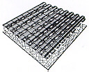
The boron fiber surface shows a “corn-cob” structure consisting of nodules separated by boundaries. The nodule size varies during the course of fabrication. In a very general way, the nodules start as individual nuclei on the substrate and then grow outward in a conical form until a filament diameter of 80-90 micron is reached, above which the nodules seem to decrease in size. Occasionally, new cones may nucleate in the material, but they always originate at an interface with a foreign particle or inclusion.
Residual Stresses
Boron fibers have inherent residual stresses that have their origin in the process of chemical vapor deposition. Growth stresses in the nodules of boron, stresses induced by the diffusion of boron into the tungsten core, and stresses generated by the difference in the coefficient of expansion of deposited boron and tungsten boride core, all contribute to the residual stresses and thus can have a considerable influence on the fiber mechanical properties. The compressive stresses on the fiber surface are due to the quenching action involved in pulling the fiber out from the chamber. Morphologically, the most conspicuous aspect of these internal stresses would appear to be the frequently observed radial crack, from within the core to just inside the outer surface, in the transverse section of these fibers.
Fracture Characteristics
It is well known that brittle materials show a distribution of strengths rather than a single value. Imperfections in these materials lead to stress concentrations much higher than the applied stress levels. Because the brittle material is not capable of deforming plastically in response to these stress concentrations, fracture ensues at one or more such sites. Boron fiber is indeed a very brittle material and cracks originate at preexisting defects located at the boron-core interface or at the surface. As mentioned in the beginning, boron fiber in itself is a composite fiber. It is a consequence of the discontinuity between the properties of boron and tungsten borides. This discontinuity cannot be eliminated totally but can be minimized by a proper core formation and proper bonding between the core and the boron deposit.
Properties and Applications of Boron Fibers
Due to the composite nature of the boron fiber, complex internal stresses and defects such as voids and structural discontinuities result from the presence of a core and the deposition process. Thus, one would not expect boron fiber strength to equal the intrinsic strength of boron. The average tensile strength of boron fiber is 3-4 GPa, while its Young’s modulus is between 380 and 400 GPa.
An idea of the intrinsic strength of boron is obtained in a flexure test. It would be expected that in flexure, assuming the core and interface to be near the neutral axis, critical tensile stresses would not develop at the core or interface. Flexure tests on boron fibers lightly etched to remove any surface defects gave a strength of 14 GPa. Without etching the strength was half this value.
There has been some effort at NASA Lewis Research Center to improve the tensile strength and toughness (or fracture energy) of boron fibers by making them larger in diameter. Commercially produced 142-gm diameter boron fiber shows tensile strengths less than 3.8 GPa. The tensile strength and fracture energy values of the as-received and some limited-production run larger-diameter fibers showed improvement after chemical polishing. Fibers showing strengths above 4 GPa had their fracture controlled by a tungsten-boride core, while fibers with strengths of 4 GPa were controlled by fiber surface flaws. The high-temperature treatment, improved the flber properties by putting a permanent axial contraction strain in the sheath.
Boron has a density of 2.34 g cm-3 (about 15% less than that of aluminum). Boron fiber with the tungsten core has a density of 2.6 g cm-3 for a fiber of 100 micron diameter. Its melting point is 2040°C and it has a thermal expansion coefficient of 8.3 x 10⁻⁶ oC-1 up to 315°C.
Boron Fiber composites are in use in a number of U.S. military aircraft, notably the F-14 and F-15, and in the U.S. Space Shuttle. Increasingly, boron fibers are being used for stiffening golf shafts, tennis rackets, and bicycle frames. One big obstacle to the widespread use of boron Fiber is its high cost compared to that of other fibers. A major portion of this high price is the cost of the tungsten substrate.
The role of the matrix in a fiber-reinforced composite is:
- to transfer stresses between the fibers
- to provide a barrier against an adverse environment, and
- to protect the surface of the fibers from mechanical abrasion
The matrix plays a minor role in the tensile load-carrying capacity of a composite structure. However, selection of a matrix has a major influence on the interlaminar shear as well as in-plane shear properties of the composite material. The interlaminar shear strength is an important design consideration for structures under bending loads, whereas the in-plane shear strength is important under torsional loads. The matrix provides lateral support against the possibility of fiber buckling under compression loading, thus influencing to some extent the compressive strength of the composite material. The interaction between fibers and matrix is also important in designing damage-tolerant structures. Finally, the processability and defects in a composite material depend strongly on the physical and thermal characteristics, such as viscosity, melting point, and curing temperature of the matrix.
Thermoset polymers, such as epoxies and polyesters, are in greatest commercial use, mainly because of the ease of processing with these materials. Metallic matrices are primarily considered for high temperature applications. We discuss these two categories of matrix in more detail.
Polymeric Matrix
A polymer is defined as a long-chain molecule containing one or more repeating units of atoms, joined by strong covalent bonds. A polymeric material (commonly called a plastic) is a collection of a large number of polymer molecules of similar chemical structure (but not of equal length). In the solid state, these molecules are frozen in space, either in a random fashion (for amorphous polymers) or in a mixture of random and orderly (folded) fashions (for semicrystalline polymers. However, on a submicroscopic scale, various segments in a polymer molecule may be in a state of random excitation. The frequency, intensity, and number of these segmental motions increase with increasing temperature, giving rise to the temperature-dependent properties of a polymeric solid.
Matrix Materials
Polymeric
Thermoset polymers (resins)
- Epoxies: principally used in aerospace and aircraft applications
- Polyester, vinyl esters: commonly used in automotive, marine, chemical, and electrical applications
- Phenolics: used in bulk molding compoundsPolyimides, polybenzimidazoles (PBD), potyphenylquinoxatine (PPQ); for high-temperature aerospace applications (temperature range: 250-400°C)
Thermoplastic polymers
- Nylons (such as nylon 6, nylon 6,6), thermoplastic polyesters (such as PET, PBT), polycarbonate (PC), polyacetals: used with discontinuous fibers in injection molded articles
- Polyamide-imide (PAI), polyether-ether ketone (PEEK), polysulfone (PSUL), polyphenylene sulfide (PPS), polyether imide (PEI): suitable for moderately high-temperature applications with continuous fibers
Metallic
- Aluminum and its alloys, titanium alloys, magnesium alloys, copper-based alloys, nickel-based superalloys, stainless steel: suitable for high-temperature applications (temperature range: 300-500°C)
Ceramic
- Aluminum oxide (Al203), carbon, silicon carbide (SiC), silicon nitride (Si3N4): suitable for high-temperature applications
Thermoplastic and Thermoset Polymers
Polymers are divided into two broad categories: thermoplastics and thermosets. In a thermoplastic polymer, individual molecules are linear in structure with no chemical linking between them. They are held in place by weak secondary bonds (intermolecular forces), such as Vander Waals bonds and hydrogen bounds. With the application of heat and pressure, these intermolecular bonds in a solid thermoplastic polymer can be temporarily broken, and the molecules can be moved relative to each other to flow into new positions. Upon cooling, the molecules freeze in their new positions, restoring the secondary bonds between them and resulting in a new solid shape. Thus, a thermoplastic polymer can be heat softened, melted, and reshaped (postformed) as many times as desired.
In a thermoset polymer, on the other hand, the molecules are chemically joined together by cross-finks, forming a rigid, three-dimensional network structure. Once these cross-links are formed during the polymerization reaction (also called the curing reaction), the thermoset polymer cannot be melted and reshaped (postformed) by the application of heat and pressure. However, if the number (frequency) of cross-links is low, it may still be possible to soften them at elevated temperatures.
Unique Characteristics of Polymeric Solids
There are two unique characteristics of polymeric solids that are not observed in metals under ordinary conditions, namely, that their mechanical properties depend strongly upon ambient temperature and loading rate (time). Near the glass transition temperature, denoted by Tg, the polymeric material changes from a hard, sometimes brittle (grass like) solid to a soft, tough leather like) solid. Over a temperature range around Tg, its modulus is reduced by as much as five orders of magnitude. Near this temperature, the material is also highly viscoelastic. Thus, when an external load is applied, it exhibits an instantaneous (elastic) deformation followed by a (slow) viscous deformation. With increasing temperature, the polymer changes into a rubberlike solid capable of undergoing large, elastic deformations under external loads. As the temperature is increased further, both amorphous and semiicrystalline thermoplastics achieve highly viscous liquid states, with the latter showing a sharp transition at the crystalline melting point, denoted by Tm Tg. However, for a thermosetting Polymer, no melting occurs; and finally burns at very high temperatures instead, it chars. The glass transition temperature of a thermoset can be controlled by for very highly cross-linked polymers; the glass transition and accompanying softening may not be observed.
The mechanical characteristics of a polymeric solid depend on the ambient temperature as well as its value relative to the glass transition temperature of the Polymer. If the ambient temperature is above Tg, the polymeric solid exhibits low surface hardness, low modulus, and high ductility’ At temperatures below Tg, the segmental motion in a polymer plays an important role. If the molecular structure of a polymer allows many segmental motions, it behaves in a ductile manner even below Tg. Polycarbonate (PC), Polyethylene terephthalate(PET), and various nylons fall into this category. If, on the other hand, the segmental motions are restricted, as in Polymethylmethacrylate (PMMA), polystyrene (PS) and many thermoset Polymers, it shows essentially a brittle failure. The effect of loading rate on the mechanical properties of a Polymer is opposite to that due to temperature. At high loading rates or short durations of loading, the Polymeric solid behaves in a rigid, brittle (grasslike) manner. At low loading rates or long durations of loading, the same material may behave in a ductile manner and show high toughness values.
Creep and Stress Relaxation
The viscoelastic characteristic of a polymeric solid is best demonstrated by creep and stress relaxation tests. In creep tests, a constant stress is maintained on a specimen while its deformation (strain) is monitored as a function of time. In stress relaxation tests, a constant deformation (strain) is maintained while the stress on the specimen is monitored as a function of time. Both tests are performed at various ambient temperatures of interest Typical creep and stress relaxation diagrams exhibit an instantaneous elastic response followed by a delayed, viscous response during both loading and unloading of the specimen.
Heat Deflection Temperature
Softening characteristics of various polymers are often compared by their heat deflection temperatures (HDT). Measurement of HDT is described in ASTM test method D648-72. In this test, a plastic (polymeric) bar of rectangular cross section is loaded as a simply supported beam (inside a suitable nonreacting liquid medium, such as mineral oil. The load on the bar is adjusted to create a maximum fiber stress of either 1.82 MPa (264 psi) or 0.455 MPa (66 psi). The center deflection of the bar is monitored on a dial gauge as the temperature of the liquid medium is increased at a uniform rate of 2 + 0.20C/min. The temperature at which the bar deflects 0.25 mm (0.01 in.) from its initial room temperature deflection is called the heat deflection temperature at the specific fiber stress.
Although HDT is widely reported in the plastics product literature, it should not be used in predicting the elevated temperature performance of a polymer. It is used mostly for quality control and material development purposes. It should be pointed out that HDT is not a measure of glass transition temperature. For glass transition temperature measurements, such methods as differential scanning calorimetry (DSC) or differential thermal analysis (DTA) are used.
Selection of Matrix: Thermosets vs. Thermoplastics
The primary consideration in the selection of a matrix is its basic mechanical properties. For high-performance composites, the most desirable mechanical properties of a matrix are:
- High tensile modulus, which influences the compressive strength of the composite
- High tensile strength, which controls the intraply cracking in a composite Laminate
- High fracture toughness, which controls ply delamination and crack growth
For a polymeric matrix composite, there may be other considerations, such as good dimensional stability at elevated temperatures, and resistance to moisture and solvents. The former usually means that the polymer must have a high glass transition temperature Tg. In practice, the glass transition temperature should be higher than the maximum use temperature. Resistance to moisture and solvent means that the polymer should not dissolve, swell, crack (craze), or otherwise degrade in hot/wet environments or when exposed to solvents. Some common solvents in aircraft applications are jet fuels, deicing fluids, and paint strippers. Similarly, gasoline, motor oil, and antifreeze are common solvents in the automotive environment.
Traditionally, thermoset polymers (also called resins) have been used as a matrix material for fiber-reinforced composites. Starting materials used in the polymerization of thermoset, polymers are usually low-molecular-weight liquid chemicals with very low viscosities. Fibers are either pulled through or immersed in these chemicals before the polymerization reaction begins. Since the viscosity of the polymer at the time of fiber incorporation is very low, it is possible to achieve a good wet-out between the fibers and the matrix without the aid of high temperature or pressure. Among other advantages of using thermoset, polymers are their thermal stability and chemical resistance. They also exhibit much less creep and stress relaxation than thermoplastic polymers. The disadvantages are their limited storage life (before the final shape is molded) at room temperature, long fabrication time in the mold (where the polymerization reaction is carried out to completion and a solid part is obtained), and low strains-to-failure, which also contribute to their low impact strengths.
The most important advantage of thermoplastic polymers over thermoset polymers is their high impact strength and fracture resistance, which in turn impart an excellent damage tolerance characteristic to the composite material. In general, thermoplastic polymers have higher strains-to-failure than thermoset polymers, which may provide a better resistance to matrix microcracking in the composite laminate. Other advantages of thermoplastic polymers are
- Unlimited storage (shelf) life at room temperature
- Shorter fabrication time
- Postformability (e.g., by thermoforming)
- Ease of repair by welding, solvent bonding, etc.
- Ease of handling (no tackiness)
- Can be recycled
In spite of such distinct advantages, the development of thermoplastic matrix has been slower than that of thermoset matrix. Because of their high melt or solution viscosities, incorporation of continuous fibers into thermoplastic matrices is difficult. Commercial engineering thermoplastic polymers, such as nylons and polycarbonate, are of very limited interest in structural applications because they exhibit lower creep resistance and thermal stability than thermoset polymers. Recently, a number of thermoplastic polymers have been developed that possess high heat resistance. They are currently being explored as potential matrix materials for high-performance composite structures.
Metal Matrix
Metal matrix has the advantage over polymeric matrix in applications requiring a long-term resistance to severe environments, such as high temperature. The yield strength and modulus of most metals are higher than those for polymers, which is an important consideration for applications requiring high transverse strength and modulus as well as compressive strength for the composite. Another advantage of using metals is that they can be plastically deformed and strengthened by a variety of thermal and mechanical treatments. However, metals have a number of disadvantages, namely, they have high specific gravities, high melting points (therefore, high process temperatures), and a tendency toward corrosion at the fiber/matrix interface.
The two most commonly used metal matrices are based on aluminum and titanium. Both of these metals have comparatively low specific gravities and are available in a variety of alloy forms. Although magnesium is even lighter, its great affinity toward oxygen promotes atmospheric corrosion and makes it less suitable for many applications. Beryllium is the lightest of all structural metals and has a tensile modulus higher than that of steel. However, it suffers from extreme brittleness, which is the reason for its exclusion as a potential matrix material. Nickel- and cobalt-based superalloys have also been used as matrix; however, the alloying elements in these materials tend to accentuate the oxidation of fibers at elevated temperatures.
Aluminum and its alloys have attracted the most attention as matrix material in metal matrix composites. Commercially, pure aluminum has been used for its good corrosion resistance. Aluminum alloys, such as 201, 6061, and 1100, have been used for their higher tensile strength-weight ratios. Carbon fiber is used with aluminum alloys; however, at typical fabrication temperatures of 500’C or higher, carbon reacts with aluminum to form aluminum carbide (Al4C3), which severely degrades the mechanical properties of the composite. Protective coatings of either titanium boride (TiB2) or sodium are used on carbon fibers to reduce the problem of fiber degradation as well as to improve their wetting with the aluminum alloy matrix. Carbon fiber-reinforced aluminum composites are inherently prone to galvanic corrosion, in which carbon fibers act as a cathode owing to a corrosion potential of 1 V higher than that of aluminum. A more common reinforcement for aluminum alloys is SiC.
Titanium alloys that are most useful in metal matrix composites are alpha, beta alloys (e.g., Ti-6Al-9V) and metastable beta alloys (e.g., Ti-IOV-2Fe-3AI). These titanium alloys have higher tensile strength-weight ratios as well as better strength retention at 400-5000C over those of aluminum alloys. The thermal expansion coefficient of titanium alloys in closer to those for reinforcing fibers, which reduces the thermal mismatch between them. One of the problems with titanium alloys is their high reactivity with boron and A1203 fibers at normal fabrication temperatures. Borsic (boron fibers coated with silicon carbide) and silicon carbide (SiC) fibers show less reactivity with titanium. Improved tensile strength retention is obtained by coating boron and SiC fibers with carbon-rich layers.
Thermoset Matrix
Epoxy
Starting materials for epoxy matrix are low-molecular-weight organic liquid resins containing a number of epoxide groups, which are three-membered rings of one Oxygen atom and two carbon atoms. Common starting material is diglycidy, ether of bisphenol A (DGEBA), which contains two epoxide groups, one at each end of the molecule. Other ingredients that may be mixed with the starting liquid are diluents to reduce its viscosity flexbilizers to improve the impact strength of the cured epoxy matrix.
The polymerization (curing) reaction to transform liquid resin to the solid state is initiated by adding small amounts of a reactive curing agent just prior to incorporating fibers into the liquid mix. One such curing agent is diethylenetriamine (DETA). Hydrogen atoms in the amine (NH2) groups of a DETA molecule react with the epoxide groups of DGEBA molecules. As the reaction continues, DGEBA molecules form crosslinks with each other and a three-dimensional network structure is slowly formed. The resulting material is a solid epoxy resin.
If the curing reaction is slowed by external means (e. g., by lowering the reaction temperature) before all the molecules are cross-linked, the resin would exist in B-stage form. At this stage, cross-links have formed at widely spaced points in the reactive mass. Hardness, tackiness, and the solvent reactivity of the B-staged resin depend on the degree of cure advancement. The B-staged resin can be transformed into a hard, insoluble mass by completing the cure later.
Curing time (also called pot life) and temperature to complete the polymerization reaction depend on the type and amount of curing agent. With some curing agents, the reaction initiates and proceeds at room temperature, but with others, elevated temperatures are required. Accelerators are sometimes added to the liquid mix to speed up a slow reaction and shorten the curing time.
The properties of a cured epoxy resin depend principally on the cross-link density (spacing between successive cross-link sites). In general, the tensile modulus, glass transition temperature, and thermal stability as well as chemical resistance are improved with increasing cross-link density, but the strain-to-failure and fracture toughness are reduced. Factors that control the cross-link density are the chemical structure of the starting liquid resin (e.g., number of epoxide groups per molecule and spacing between epoxide groups), functionality of the curing agent (e.g., number of active hydrogen atoms in DETA), and the reaction conditions, such as temperature and time.
The continuous use temperature for DGEBA-based epoxies is 1500C or less. Higher heat resistance can be obtained with epoxies based on novolac and cycloaliphatics, for example, which have a continuous use temperature ranging up to 2500C. In general, the heat resistance of an epoxy is improved if it contains more aromatic rings in its basic chain.
Epoxy matrix, as a class, has the following advantages over other thermoset matrices:
- Wide variety of properties, since a large number of starting materials, curing agents, and modifiers are available
- Absence of volatile matters during cure
- Low shrinkage during cure
- Excellent resistance to chemicals and solvents
- Excellent adhesion to a wide variety of fillers, fibers, and other substrates
The principal disadvantages are its relatively high cost and long cure time. Currently, the primary epoxy resin used in the aerospace industry is based on tetraglycidal diaminodiphenyl methane (TGDDM). It is cured with diaminodiphenyl sulfone (DDS) with or without an accelerator. The TGDDM/DDS system is used due to its relatively high glass transition temperature (240-2600C, compared to 180-1900C for DGEBA systems) and good strength retention even after prolonged exposure to elevated temperatures. Prepregs made with this system can be stored for a longer time period due to relatively low curing reactivity of DDS in the “B-staged” resin. Limitations of the TGDDM system are their poor hot/wet performance, low strain-to-failure and high level of atmospheric moisture absorption (due to its highly polar molecules). High moisture absorption reduces its glass transition temperature as well as its modulus and other mechanical properties.
Typical Properties of Cast Epoxy Resin (at 23°C)
- Specific gravity 1.2-1.3
- Tensile strength, MPa (psi) 55-130 (8000-19,000)
- Tensile modulus, GPa (106 Psi) 2.75-4.10 (0.4-0.595)
- Poisson’s ratio 0.2-0.33
- Coefficient of thermal expansion, 10-6m/m per 0C (10-6 in./in. per 0F)50-80 (28-44)
- Cure shrinkage, % 1-5
Although the problems of moisture absorption and hot/wet performance are reduced by changing the resin chemistry, brittleness or low strain-to-failure is an inherent problem of any highly cross-linked resin. Improvement in the matrix stran-to-falure and fracture toughness is considered essential for damage tolerant composite laminates. For epoxy resins, this can be accomplished by adding a small amount of highly reactive carboxyl, terminated butadiene-acrylonitrile (CTBN) liquid elastomer which forms a second phase in the cured matrix and impedes its microcracking. Although the resin is toughened, its glass transition temperature, modulus, and tensile strength as well as solvent resistance are reduced. This Problem is Overcome by blending epoxy with a tough thermoplastic resin, such as polyethersulfone, but the toughness improvement depends on properly matching the epoxy and thermoplastic resin functionlities, their molecular weights, etc.
Polyester
The starting material for a thermoset polyester matrix is an unsaturated polyester resin that contains a number of C = C double bonds. It is prepared by the reaction of maleic anhydride and ethylene or propylene glyco. Saturated acids, such as isophthalic or orthophthalic acid, are also added to modify the chemical structure between the cross-linking sites; however, they do not contain any C = C double bonds. The resulting polymeric liquid is dissolved in a reactive (polymerizable) diluent, such as styrene, which reduces its viscosity and makes it easier to handle. The diluent also contains C = C double bonds and acts as a cross-linking agent by bridging adjacent polyester molecules at their unsaturation points. Trace amounts of an inhibitor, such as hydroquinone or benzoquinone, are added to the liquid mix to prevent premature polymerization during storage.
The curing reaction for polyester resins is initiated b adding small quantities of a catalyst, such as organic peroxide or an aliphatic azo compound, to the liquid mix. With the application of heat (in the temperature range of 107-163 0C), the catalyst decomposes rapidly into free radicals, which react (mostly) with the styrene molecules and break their C = c bonds. Styrene radicals, in turn, join with the Polyester molecules at their unsaturation points and eventually form cross-links between them. The resulting material is a solid polyester resin.
The curing time for Polyester resins depends on the decomposition rate of the catalyst, which can be increased by increasing the curing temperature. However, for a given resin-catalyst system, there is an optimum temperature at which all of the free radicals generated from the catalyst are utilized in curing the resin. Above this optimum temperature, free radicals are formed so rapidly that wasteful side reactions occur and deterioration of the curing reaction is observed. At temperatures below the optimum, the curing reaction is very slow. The decomposition rate of a catalyst can be increased by adding small quantities of accelerator, such as cobalt naphthanate (which essentially acts as catalyst for the primary catalyst.
As in the case of epoxy resins, the properties of polyester resins depend strongly on the cross-link density. The modulus, glass transition temperature and thermal stability of cured polyester resins are improved by increasing the cross-link density, but the strain-to-failure and impact energy are reduced. The major factor influencing the cross-link density is the number of unsaturation points in an uncured polyester molecule. The simplest way of controlling the frequency of unsaturation points is to vary the weight ratio of various ingredients used for making unsaturated polyesters. For example, the frequency of unsaturation in an isophthalic polyester resin decreases as the weight ratio of isophthalic acid to maleic anhydride is increased. The type of ingredients also influences the Properties and/or processing characteristics of polyester resins, For example, terephthalic acid generally provides a higher heat deflection temperature than either isophthalic or orthophthalic acids, but it has the slowest reactivity of the three phthalic acids, Adipic acid, if used instead of any of the phthalic acids, lowers the stiffness of polyester molecules, since it does not contain an aromatic ring in the backbone. Thus, it can be used as a flexibilizer for poleester resins. Another ingredient that can also lower the stiffness is diethylene glycol. Propylene glycol, on the other hand, makes the polyester resin more rigid, since the pendent methyl groups in its structure restrict the rotation of polyester molecules.
The amount and type of diluent are also important factors in controlling the properties and processing characteristics of polyester resins. Styrene is the most widely used diluent because it has low viscosity, high solvency, and low cost. Its drawbacks are flammability and Potential (carcinogenic) health hazard due to excessive emissions. Increasing the amount of Styrene reduces the modulus of the cured polyester resin since it increases the space between Polyester molecules. Because styrene also contributes unsaturation points, a higher styrene content in the resin solution increases the total amount of unsaturation and, consequently, the curing time is increased. An excessive amount of styrene tends to promote self-polymerization (i.e., formation of polystyrene) and causes polystyrene-like properties to dominate the cured Polyester resin.
Polyester resins can be formulated in a variety of properties ranging from hard, brittle to soft, and flexible. Its advantages are low viscosity, fast cure time, and low cost. Its properties are generally lower than those for epoxies. The principal disadvantage of polyesters over epoxies is their high volumetric shrinkage. Although this allows easier release of parts from the mold, the difference in shrinkage between the resin and fibers results in uneven depressions (called sink marks) on the molded surface. The sink marks are undesirable for exterior surfaces requiring high gloss and good appearance (e.g., class A quality in automotive body components). One way of reducing these surface defects is to use low-shrinkage (also called low-profile) polyester resins that contain a thermoplastic component (such as polystyrene or polymethyl methacrylate). As curing proceeds, phase changes in the thermoplastic component allow the formation of microvoids that compensate for the normal shrinkage of the polyester resin.
Vinyl Ester
The starting material for a vinyl ester matrix is an unsaturated vinyl ester resin produced by the reaction of an unsaturated carboxylic acid, such as methacrylic or acrylic acid, and an epoxy resin. The C = C double bonds (unsaturation points) occur only at the ends of a vinyl ester molecule, and therefore, cross-linking can take place only at the ends. Because of fewer cross-links, a cured vinyl ester resin is more flexible and has higher fracture toughness than a cured polyester resin. Another unique characteristic of a vinyl ester molecule is that it contains a number of OH (hydroxyl) groups along its length. These OH groups can form physical (hydrogen) bonds with similar groups on a glass fiber surface resulting in excellent wet-out and good adhesion with glass fibers.
Vinyl ester resins, like unsaturated polyester resins, are dissolved in styrene monomer, which reduces their viscosity. During polymerization, styrene also coreacts with the vinyl ester resin to form cross-links between the unsaturation points in adjacent vinyl ester molecules. The curing reaction for vinyl ester resins is similar to that for unsaturated polyesters.
Typical Properties of Cast Thermoset Polyester Resins (at 23°C)
- Specific gravity 1.1-1.4
- Tensile strength, MPa (psi) 34.5-103.5 (5000-15,000)
- Tensile modulus, GPa (106psi) 2.1-3.45 (0.3-0.5)
- Elongation, % 1-5
- Heat Deflection Temperature, °C (°F) 60-205 (140-400)
- Cure shrinkage, % 5-12
Vinyl ester resins possess good characteristics of epoxy resins, such as excellent chemical resistance and tensile strength, and of unsaturated polyester resins such as low viscosity and fast curing. However, the volumetric shrinkage of vinyl ester resins is in the range of 5-10%, which is higher dm that of the parent epoxy resins. They also exhibit only moderate adhesive strengths compared with epoxy resins. The tensile and flexural properties of cured vinyl ester resins do not vary appreciably with the molecular weight and type of epoxy resin or other coreactants. However, the heat deflection temperature and thermal stability can be improved by using heat-resistant epoxy resins, such as phenolic-novolac types.
Bismaleimides and Other Thermosetting Polyimides
Bismaleimides(BMIs), PMR- 15 (for polymerization of monomer reactants), and ACTP (for acetylene terminated polyimide) are examples of thermosetting polyimides. Among these, bismaleimides are suitable for applications requiring a service temperature of 127-2320C. PMR and ACTP can be used up to 288 and 3160C, respectively. PMR and ACTP also have exceptional thermo-oxidative stability and show only 20% weight loss over a period of 1,000 h at 3160C in flowing air.
Thermosetting polyimides are obtained by addition polymerization of liquid monomeric or oligomeric imides to form a cross-linked infusible structure. They are available either in solution form or in hot melt liquid form. Fibers can be coated with the liquid imides or their solutions before the cross-linking reaction. On curing, they not only offer high temperature resistance, but also high chemical and solvent resistance. However, these materials are inherently very brittle due to their densely cross-linked molecular structure. As a result, their composites are prone to excessive microcracking. One useful method of reducing their brittleness without affecting their heat resistance is to combine them with one or more tough thermoplastic polyimides. The combination produces a semi interpenetrating network (semi-IPN) polymer, which retains the easy processability of a thermoset and exhibits the good toughness of a thermoplastic. Although the reaction time is increased, this helps in broadening the processing window, which otherwise is very narrow for some of these polyimides and causes problems in manufacturing large or complex composite parts.
Physical Properties of Cast Vinyl Ester Resins (at 23°C)
- Specific gravity 1.12-1.32
- Tensile strength, MPa (psi) 73-81 (10,500-11,750)
- Tensile modulus, GPa (106Psi) 3-3.5 (0.44-0.51)
- Elongation, % 3.5-5.5
- HDT, °C (°F) 93-135 (200-275)
- Cure shrinkage, % 5.4-10.3
Bismaleimides are the most widely used thermosetting polyimides in the advanced composite industry. Bismalemide monomers (prepolymers) are prepared by the reaction of maleic anhydride with a diamine. A variety of bismaleimide monomer can be prepared by changing the diamine. BMI monomers are mixed with reactive diluents to reduce their viscosity and other comonomers, such as vinyl, acrylic, and epoxy, to improve the toughness of cured BMI. The handling and processing techniques for BMI resins are similar to those for epoxy resins. The curing of BMI occurs through addition-type homo or copolymerization that can be thermally induced at 170-190 0C.
Thermoplastic Matrix
The molecules in thermoplastic polymers contain rigid aromatic rings that give them a relatively high glass transition temperature Tg, and an excellent dimensional stability at elevated temperatures. The actual value of Tg depends on the size and flexibility of other chemical groups or linkages in the chain.
Polyether Ether Ketone (PEEK)
Continuous carbon fiber-reinforced PEEK composites are known in the industry as aromatic polymer composite or APC. PEEK is a semicrystalline polymer with a maximum achievable crystallinity of 48% when it is cooled slowly from its melt- Amorphous PEEK is produced if the melt is quenched. At normal cooling rates, the crystallinity is between 30 and 35 %. The presence of fibers in PEEK composites tends to increase the crystallinity to a higher level, since the fibers act as nucleation sites for crystal formation. Increasing crystallinity increases both modulus and yield strength of PEEK, but reduces its strain-to-failure.
PEEK has a glass transition temperature of 143°C and a crystalline melting point of 335°C. Melt processing of PEEK requires a temperature range of 370-400°C. The maximum continuous use temperature is 250°C. PEEK is the foremost thermoplastic matrix that may replace epoxies in many aerospace composites. The outstanding property of PEEK is its high fracture toughness, which is 50-100 times higher than epoxies. Another important advantage of PEEK is its low water absorption, which is less than 0.5% at 23°C compared to 4-5% for conventional aerospace epoxies. Being semicrystalline, it does not dissolve in common solvents. However, it may absorb some of these solvents, most notably methylene chloride. The amount of solvent absorbed decreases with increasing crystallinity.
Polyphenylene Sulfide (PPS)
PPS is a semicrystalline polymer and is normally 65 % crystalline. It has a glass transition temperature of 85°C and a crystalline melting point of 285°C. The relatively low Tg of PPS is due to the flexible sulfide linkage between the aromatic rings. Its relatively high crystallinity is attributed to the chain flexibility and structural regularity of its molecules.
Melt processing of PPS requires heating the polymer in the temperature range of 300-345 0C. The continuous use temperature is 2400C. It has excellent chemical resistance.
Polysulphone
Polysulfone has a glass transition temperature of 185°C and a continuous use temperature of 160°C. The melt processing temperature is between 310 and 410°C. It has a high tensile strain-to failure (50-100%) and an excellent hydrolytic stability under hot/wet conditions (e.g., in steam). Although it has good resistance to mineral acids, alkalies, and salt solutions, it will swell, stress-crack, or dissolve in Polar Organic solvents such as ketones, chlorinated hydrocarbons, and aromatic hydrocarbons.
Thermoplastic Polyimides
Thermoplastic polyimides are linear polymers derived by condensation polymerization of a polyamic acid and an alcohol. Depending on the types of the polyamic acid and alcohol, various thermoplastic polyimides can be produced. The chemical reaction takes place in presence of a solvent and produces water as its by-product. The resulting polymer has a high melt viscosity and must be processed at relatively high temperatures. Unlike thermosetting polyimides, they can be reprocessed by the application of heat and pressure. Polyetherimide (PEI) and polyamide-imide (PAI) are melt processable thermoplastic polyimides.Both are amorphous Polymers with high glass transition temperatures, 217°C for PEI and 280°C for PAI. The processing temperature is 350°C or above. Two Other thermoplastic polyimides, known as K polymers and LARC-TPI (for Langley Research Center Thermoplastic imide), are generally available as prepolymers dissolved in suitable solvents. In this form, they have low viscosities so that the fibers can be coated with their prepolymers to produce flexible prepregs. Curing, which for these Polymers means imidization or imide ring formation, requires heating up to 300°C or above.
The glass transition temperatures for K polymer and LARC-TPI are 250 and 2650C respectively. Both are amorphous polymers, and offer excellent heat and solvent resistance. Since their molecules are not cross-linked, they are not as brittle as thermosetting polymers. They are processed with fibers from low-viscosity solutions much like the thermosetting resins; yet, after imidization, the can be made to flow and be shape formed like conventional thermoplastics by heating them over their Tg. This latter characteristic is due to the presence of flexible chemical groups between the stiff, fused-ring imide groups in their backbones. In LARC-TPI, for example, the source of flexibility are the carboxyl groups and the meta substitution of the phenyl rings in the diamine-derived portion of the chain.
COMPRESSION MOLDING is a term that encompasses several different technologies. Sheet molding compounds (SMC), structural molding compounds, and thermoplastic can all be compression molded on various specialized equipment. One attribute all compression processes have in common is the use of premanufactured material or “charge” that is pressed to shape and cured during the molding operation
The compression molding process is presently the most technologically developed and incorporate either continuous or random chopped fibers into a structural composite. The process is more rapid and complex than the labor-intensive hand lay up or liquid matched die molding methods that it often replaces, but it has a trade-off with respect to fiber alignment. Depending on component shape and charge pattern, compression molding may involve regions of high resin flow that tend to orient fibers in the flow direction. Random orientation is desirable for chopped fiber sheet molding compound and long fiber thermoplastic materials. If directional fibers are desired, flow patterns can be developed.
The compression molding process is most commonly called the SMC process in reference to the precursor sheet molding compound material it uses. The primary application of this technology in the automotive industry has been for grille opening panels and, on selected vehicles, exterior panels. Tailgates and hoods are two other examples of vehicular use of the SMC process. The entire cab of selected heavy trucks is also produced using this process.
A typical process cycle consists of placing sheets of SMC, which consist of 1 3 mm (0.5 in.) chopped glass fibers in chemically thickened thermoset resin that has a leathery consistency, into a heated mold (typically 150°C, or 300°F). The mold is closed under pressures of 7 to 14 MPa (1 to 2 ksi) for about 1 to 3 min to cure the material. Approximately 30 to 80% of the mold surface is covered by the SMC charge, and the material flows to fill the remaining cavity as the mold closes.
Materials for Sheet Manufacture
Fiber utilization in compression molding materials is very versatile. Continuous, cut length, or chopped glass fibers may be used, as well as random continuous glass mats. Carbon or aramid fibers may also be used. Sheet molding compounds can be made in various compositions and by various processes. Continuous, unidirectional molding compounds for structural components generally have 40 to 60 wt% glass fiber reinforcement. Normally, SMC for nonstructural automotive trim and body applications is 27 to 30 wt% glass fiber. Fillers are often used to minimize resin cost and lower thermal expansion of the product.
Resin chemistry has a major influence on the strength and reliability of the final composite component. Although the resin constitutes only 16 to 25 wt% of a typical SMC composite, it controls flow and moldability. Strength and corrosion resistance must be optimized by the resin selection. However, low viscosity high-acid resins are often desired for their good wetting and thickening characteristics; for example, magnesium oxide added to the resin system thickens it to a leathery consistency. The reaction takes place over a period of up to 5 days. Although epoxy resins are used in aerospace SMCs, vinyl ester and polyester resins are generally used in automotive applications because of their faster cure time and lower cost. Many SMC materials use a high reactivity, isophthalic polyester resin (for example, E980) with magnesium oxide for thickening. Ground limestone is generally used if a filler is required.
To form a component, sheets of SMC material are cut to a desired shape, the carrier film is removed, and the SMC sheets are stacked as a series in a charge pattern. For example in molding an automotive wheel nine sheets of SMC are stacked; the charge pattern is then placed between clean, preheated dies, and upon closing, the press spreads out to fill the die cavity. Normal die temperatures are 130 to 160 °C (270 to 320 °F). Typical cavity pressure varies from 4 to 21Mpa (2 to 3 ksi), depending on resin viscosity, glass fiber content, charge pattern, and mold complexity.
Cycle time ranges from 1 to 4 min, depening on component complexity, thckness, and the die clean up required. Cure time is very critical: If the resin cure exotherm is not properly controlled, cracking, blistering, or warping can occur. After all the other steps in SMC process are automated, the exotherm may well be the rate-controlling factor for thick parts of more than 10 mm (0.4 in.).
Advanced compression mold designs and molding systems are presently being developed to reduce SMC cycle time. Current minimum cycle time is about 1 min, button to button, die closed time. Tooling must be of high quality to maintain these fast molding rates and must be hardened in critical wear areas. It is also necessary in some cases to use compression molding heat transfer analysis techniques to maximize the heat transfer characterstics of the tool. Extra sets of tooling are expensive and introduce variance in part tolerance when numbers of parts must be assembled from moldings of several tools. It is therefore advantageous from several perspectives to produce parts as rapidly as possible using a minimum number of tools.
Material cost for compression molded SMC was estimated to be approximately 3.5 times the cost of steel by weight. To compete polyester composites must integrate several parts into one, to save assembly, floor space and storage costs. If suitable part integration could be accomplished, polyester SMC would compete with steel for up to 227000 units per year. To compete beyond this volume, the SMC cycle time must be reduced. Halving the cycle time would double the level at which composite components would compete with steel. Research must be done to speed up the process; eliminate SMC storage by making it on-site; and immediately recycle rejected, uncured SMC to bulk molding compound(BMC).
Many supply companies are conducting research to obtain more reproducible SMC products as well as faster cycle times. The rate of pressure application and parallelism of the molding die are being closely controlled by a microcomputer controlled flow system. Many SMC applications are for visible components requiring high quality surface finishes. Using low-profile resins and highly polished dies improves the as molded surface. Control of material flow and tooling surface (parallelism) also reduces waviness and improves appearance. A technique for obtaining better surface finish that is currently being used in many applications is called in mold coating.
To apply an in mold coating, a thermoset resin is injected into the mold after the SMC component is partially cured. To provide a space for the coating, the press is opened slightly. This opening can be conveniently achieved by using a counteracting force system or, as in case of the recently developed high pressure in mold coating systems, by injecting the coating with a slight yet pressure to compress the partially cured SMC. The thermoset resin is injected into the die and the die is reclamped. The press forces the coating to surround and impregnate any surface voids in the SMC in a uniform manner. Urethane is a common in-mold coat. The in-mold coating can eliminate some paint priming operations and significantly reduce the hand finishing required for SMC. Class A surfaces can be obtained with a minimum number of paint pops after baking. Research is currently being done to apply in mold coating to deep sections, such as fender extensions. Present technology extends to shapes such as Corvette hood outer panels and similar large, rather simple geometries. This process does not address problems that exist in areas where subsequent machining will expose new, uncoated surfaces, such as trimmed edges.
The other system in use today to improve SMC surface quality relies on a vacuum to decrease the amount of trapped air and gasses in the molded component. As the mold is closed on the SMC charge, a seal closes around the entire mold and the mold area is evacuated. As the material flows to fill the die, the vacuum enhances the natural expulsion of air and styrene vapor from the SMC material, resulting in higher surface quality and less tendency for the occurrence of subsequent defects during painting.
Process Advantages The SMC method has several advantages over methods such as hand lay up or spray up. Having the liquid resin, catalyst, and glass fiber precombined into a unit can allow better quality control over chemistry, mix, and distribution prior to forming. Using matched metal dies is a elosed mold process that gives better dimensional control and stability than open mold processes. Higher pressures require more expensive tooling than is necessary for hand lay up or spray up but less expensive tooling than is needed for stamping or injection molding.
Higher pressures during compression molding may reduce the blistering, splitting, and paint popping often encountered during paintbaking cycles in moldings made at lower pressure. The short flow lengths that are possible in compression molding tend to minimize fiber movement, and reduce stresses and tool wear, in contrast to injection molding. The process does not constrain the mold designer with sprue and runner lay outs. Absence of runners and sprues reduces resin degradation due to shear heating and eliminates reinforcement length reduction, which, in the case of injection molding, severely limits the length of reinforcement fibers. Venting tends to be uniform by force, and the dimensional stability of the formed components is better than it is for components formed by higher flow processes, such as injection molding, or by processes such as hand lay up.
Process Limitations There are disadvantages associated with both the SMC material and the compression molding process that must be recognized. A high capital investment is required for sheet forming and molding equipment. The cost of SMC material is also high because of the post finishing labor and equipment required after molding. The SMC material must be stored properly to prevent thermal and moisture degradation. Cracking and warpage of the final part may result from using at degraded SMC sheet. Also, the SMC sheet-forming line must be properly protected to prevent toxic vapor emissions. During the compression molding cycle, most problems are flow related. Finite element numerical techniques are showing promise in predicting flow of filled polymer melts of the type encountered in composite fabrication; however, these are not expected to be operational for several years. The problem areas that exist presently are residual stresses, warpage, weld lines, flow orientation of fibers, fiber kinks and folds, delamination, and breakdown of the resin paste and glass interface. While all these problems can be minimized by varying the charge pattern, cycle parameters, or SMC chemistry, the existence of this large number of variables adds complexity and cost to the process.
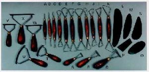 Woven materials in laminate form, are currently displacing more traditional structural forms primarily because of the availability of fibers (such as glass, carbon and aramid) whose enhanced mechanical properties in composite form surpass the property values of corresponding hardware in aluminum or steel on a strength-to-weight basis.
Autoclave curing of composites is of prime importance to manufacturing high-quality aerospace laminates. Curing is achieved through a combination of pressure, temperature and heat under inert conditions in an enclosed vessel. Processing materials must be added to a composite ply lay-up before autoclave curing. These materials control the resin content of the cured part and ensure proper application of autoclave pressure to the lay-up. The materials usually used in preparing a lay-up for autoclave curing are peel ply, separator, bleeder, barrier, breather, dam and vacuum bag. The materials are compatible with the maximum cure temperature and pressures required for the matrix system being cured.
The peel ply if used is placed immediately on top of or under the composite laminate. It is ultimately removed just before bonding or painting operations so that a clean, bondable surface is available. It is usually a woven fabric and may be either nylon, polyester, or fiberglass. The fabric is treated with a release agent that must not transfer to the laminate; otherwise, subsequent bonding or painting operations may not be satisfactory. Nylon, polyester, or fiberglass peel ply can be used with most matrix system.
A separator (release material) is placed on top of or under the laminate and peel ply. It allows volatile and air to escape from the laminate and excess resin to be bled from the laminate into the bleeder plies during cure. It also gives the cured part a smooth surface, except for porous Teflon, which gives a slightly textured surface.
The purpose of the bleeder is to absorb excess resin from the lay-up during cure, thereby producing the desired fiber volume. Fiberglass fabric or other absorbent materials or fabrics are used for this purpose. The amount of bleeder used is a function of its absorbency, the fiber volume desired in the part, and the resin content of the prepreg material used in the lay-up. In advanced composites essentially all excess resin is bled from the surface of the laminate, with edge bleeding being minimized by properly damming the lay-up edges.
To determine the correct number of plies to use:
- Determine resin content of prepreg from receiving inspection data or vendor certification data and round off to the nearest low whole number
- Obtain bleeder/prepreg ratio from the above table for the given resin content
- Multiply number of plies in the lay-up by the bleeder/ply ratio
- Round off to the nearest low whole number, this is the number of plies of fabric to be used as the bleeder.
For example, to determine the number of plies of 120-style fiberglass fabric required for a 24-ply laminate in which the graphite-epoxy has a resin content of 35.7%:
- Round off 35.7% to 35%
- According to the table, ratio of bleeder/ply of graphite-epoxy for 35% is 0.27
- 24 x 0.27 = 6.48
- Round off to 6; this is the number of bleeder plies.
The barrier is commonly placed between the bleeder plies, and breather plies. In the case of epoxy resin, it is frequently an unperforated film, so resin removal from the part, can be controlled. For resins that produce volatile by-products during cure, a film with small perforations and large spacing is used to prevent the breather materials from becoming clogged with resin and unable to perform its function.
The breather is a material placed on top of the barrier film to allow uniform application of vacuum pressure over the lay-up and removal of entrapped air or volatile during cure. It may be drapable, loosely woven fabric, or felt.
The dam is sometimes located peripherally to minimize edge bleeding. It may be an integral part of the tool or built-in position using materials such a rubber neoprene cork pressure-sensitive tape, silicone rubber or Teflon or metal bars.
The vacuum bag is used to contain any vacuum pressure applied to the lay-up before and during cure and to transmit external autoclave pressure to the part. It prevents any gaseous pressurizing medium used in the autoclave (air or inert gas) from permeating the part and causing porosity and poor or unacceptable part quality.
An autoclave system allows a complex chemical reaction to occur inside a pressure vessel according to a specified schedule in order to process a variety of materials. The evolution of materials and processes has taken autoclave operating conditions from 120 degree C and 40 psi pressure to well over 760 degree C and 10,000 psi. The materials processed in autoclaves range from metal bonding adhesives, reinforced epoxy laminates, thermoplastic laminates, metal, ceramic and carbon matrix materials, to may other aerospace and electronic components. The major elements of an autoclave system are: a vessel to contain pressure, sources to heat the gas stream and circulate it uniformly within the vessel, a subsystem to pressurize the gas stream, a subsystem to apply vacuum to parts covered by a vacuum bag, a subsystem to control operating parameters, and a subsystem to load the molds into the autoclave.
In industry autoclave curing of composites is used to improve cured product quality and reduce fabrication costs by providing:
- Process Optimization
- Reduced process inconsistencies and product rejections
- Accurate, real-time quality assurance with rapid error detection and correction
- Verification of process reaction behavior kinetics
- Nondestructive verification of cured properties
- Accurate, permanent process documentation
- Flexibility in adapting to new or modified processes
 Pultrusion is an automated process for manufacturing composite materials into continuous constant cross-sectional profiles. It is one of the most versatile composite, but it is still one of the least understood.
The term pultrusion refers to the final product and to the process. Most simply, it refers to a non homogeneous compilation of materials; pulled through a die. In virtually every case, a reinforcing fiber is integral to the finished product. The matrix used is typically a thermosetting resin, which chemically reacts when heat is introduced to create an exothermic reaction. The resulting profile is shaped to the point at which it cannot be reshaped or otherwise altered within its operating temperature range, unlike thermoplastics. In contrast, the extrusion of aluminum materials involves homogenous materials that are heated and pushed through a die, then allowed to cool into the final shape. Because the material is initially heated and then cooled, it can be heated again re-formed into another shape.
The pultrusion process has developed relatively slowly compared to other composite processes. There is a significant amount of art in combining the continuous reinforcements and resins in a continuous operation, and developing the science from the art has taken time. During the 1980s, there has been a dramatic increase in market acceptance, technology development, and pultrusion industry sophistication. Today, the number of technically competent personnel in pultrusion is sufficient to provide the base from which dramatic changes can occur. This, coupled with continual increase in cost-competitive advantages, will enable pultruded composites to become a traditional material alongside steel, wood, and aluminum before the end of the 20th century.
Process Description
Of the six key elements in the pultrusion process, the three that precede machine operation are a reinforcement handling system (referred to as creels), a resin impregnation station, and the material forming area. The machine consists of component equipment that heats, consolidates, continuously pulls, and cuts the profiles to a desired length. Although machines can produce profiles that range from 25 mm (1 in.) to 3 to 5 m (10 to 15 ft) per minute, typical line speeds are in the range of 0.6 to 1.2 m/min (2 to 4 ft/min) per cavity.
The process begins when reinforcing fibers are pulled from a series of creels. The fibers proceed through a bath, where they are impregnated with formulated resin. The resin impregnated fibers are preformed to the shape of the profile to be produced. This composite material is placed in a heated steel die that has been precision machined to the final shape of the part to be manufactured. Heat initiates an exothermic reaction in the thermosetting resin matrix. The profile is continuously pulled and exits the mold as a hot, constant cross sectional profile. The profile cools in ambient or forced air, or assisted by water as it is continuously pulled by a mechanism that simultaneously clamps and pulls. The product emerges from the puller mechanism and is cut to the desired length by an automatic, flying cutoff saw.
There are two categories of pultrusion products. The first category consists of solid rod and bar stock produced from axial fiberglass reinforcements and polyester resins; these are used to make fishing rods and electrical insulator rods, which require high axial tensile strength. The second category is structural profiles, which use a combination of axial fibers and multidirectional fiber mats to create a set of properties that meet the requirements of the application in the transverse and longitudinal directions.
More than 90% of all pultruded products are fiberglass reinforced polyester. When better corrosion resistance is required, vinyl ester resins are used. When a combination of superior mechanical and electrical properties is required, epoxy resin is used. Higher temperature resistance and superior mechanical properties generally dictate the use of epoxy resins reinforced with aramid or carbon fibers.
Process Advantages
Pultruded composites exhibit all of the features produced by other composite processes, including High strength-to-weight ratio Corrosion resistance Electrical Insulation Dimensional Stability. Additional advantages are inherent in this process. One is that any transportable length can be produced, because of its axial nature, including small diameter fiber optic cable core that is 2.2 km (1.4 miles) long, which can be wound on a spool after pultrusion.
Another advantage is that complex, thin wall shapes, such as those extruded in aluminum, or polyvinyl chloride (PVC), are now possible because of recent process technology advances. Hollow sections can be produced by using cantilevered steel mandrels. A third advantage is that wire, wood, or foam inserts can be encapsulated on a continuous basis in pultruded products.
In addition to symmetrical walls, which are always easier to pultrude, variable wall thicknesses in a constant cross section can be pultruded. A fourth advantage of the process, which is less obvious, is its ability to use a wide variety of reinforcement types, forms, and styles with many thermosetting resins and fillers. Virtually no other composite process offers as much versatility as pultrusion. Reinforcements can be placed precisely where they are needed for mechanical strength and can be consistently repeated.
Finally, pultruded shapes can be made as large as required because equipment can be built in any size. A corollary advantage of larger equipment is its ability to produce multiple cavities of the same or different profiles, which enables pultrusion to compete with traditional materials because of a relatively low labor cost. The cost of dies for pultruded shapes is also low compared to other composite processes.
Applications
The versatility of the process has enabled pultrusions to penetrate such market areas as land transportation, construction, marine, corrosion resistant equipment, electrical/electronic, consumer appliances/business equipment, aircraft, and specialties. With the newest forming technology, pultrusion can produce nearly any constant cross-sectional shape that can be extruded. Aluminum extrusions account for approximately 15% of all of the aluminum consumed, while pultrusions account for only 5% of all reinforced plastics produced; thus, pultrusion has much growth potential.
There are several markets in which pultruded profiles have made a significant penetration that is not tied to just price competitiveness. Pultruded products are successful because they provide corollary advantages that are not available with traditional competitive materials.
The highest volume application of pultrusion is the fabrication of nonconductive ladder rails for in plant and communication utility use. Corrosion resistant fiberglass sucker rods have replaced steel in the extraction of oil. Semiflexible highway delineator posts that deflect without permanent deformation are used instead of rigid cold rolled steel posts with plastic reflectors.
In highly corrosive environments, pultruded grating systems have become the standard because of their durability, replacing steel, aluminum, and even stainless steel systems. They are also used in elevated walkways and on steps where the supports are structural profiles, such as l beams, channels, angles, and tubular shapes, that are made to the same dimensions as steel or aluminum supports. Cable trays of steel are being replaced by pultruded composite cable trays because of their superior corrosion resistance and better electrical insulation values.
Pultruded solid rectangular and square bars are being used in transformers to separate the windings and to permit air circulation. Utility market applications include guy strain insulators, stand-off insulators, hot line maintenance tools, and the booms for electrical bucket trucks. Other electrical applications include tool handles, bus bar insulator supports, fuse tubes, and lighting poles.
Dunnage bars that separate and isolate loads in trucks and railcars have been made from pultruded lineals for many years. The back doors that roll into the roof of the truck are now also pultruded, as are the structural Z sections between the inner and outer walls of a refrigerated truck trailer. In many buses, the luggage rack is pultruded. Hollow sections within the rack allow air to be passed for heating or cooling. Because of its continuous nature, the process produces the rack in one piece to span the length of the bus. In other rapid transit applications, continuous lengths of coverboard are pultruded in one piece to cover the current carrying third rail on rapid transit systems. Because of the design flexibility of composite profiles, the shape is designed to snap over the rail and yet support a load dropped from above.
Technical Processes
The basic elements of all pultrusion machines are very similar, but there are differences in the selection of heating components, drive trains, clamping devices, and cutoff saws. A pultruder strives for a common denominator in establishing the processing system and its corresponding process control. Several commercial suppliers are available to provide a full range of hardware as well as process control features. These features help to bridge the gap between the art and experience of the established pultruders and the new companies entering the field.
Material In Feed
Reinforcements are provided in packages designed for the best continuous run out of its material form. Continuous glass rovings are provided in center pull packages that weigh 15 to 25 kg (30 to 50 lb) and are designed for a bookshelf style creel. Creels of 100 or more packages are common and may be stationary or mobile. The glass roving is usually drawn from the package through a series of ceramic textile thread guides or drilled carding plates of steel or plastic. This allows them to be pulled to the front of the creel while maintaining alignment and minimizing fiber breakage. Some creel designs allow multiple guide eyes (bushings) or guide bars to tailor the tension to each roving. The ease of servicing or replacing roving packages must be considered in selecting a creel design and package capacity.
Some fiberglass rovings are available as centerpull twistless; that is, the natural twist as a consequence of winding has been offset by a built in reverse twist. Continuous fibers of glass, carbon, and organic polymers can also be supplied on packages with cardboard cores designed for outside pay out to avoid twist. This style of package dictates the use of a multiple spindle creel design in which the packages are oriented horizontally. Multiple bushings are again used to guide and protect fibers as they are delivered to the front of the creel. An additional consideration of package rotation and the resulting tension necessitates the use of a spindle bearing to provide uniform tension regardless of package size. Because packages in this configuration are usually smaller, a greater number of packages may be found on such a creel design.
The continuous fiber creels are usually the first station on a process line. Directly after the roving creels is a creel designed to accommodate rolls of mat, fabric, or veil. The roll materials are usually supplied in diameters between 305 and 610 mm (12 and 24 in.) with cores of 75 or 100 mm (3 or 4 in. ) in inside diameter. The creel must be able to accommodate both the size of the roll and the inside diameter of the core, along with appropriate spindle spacing and core bushings. The ability to lock the position of the roll in the desired location will ensure proper delivery of the material to the desired location. In some cases, it is also necessary to provide for the pay out of web material in a vertical, rather than a horizontal, format. This requires independent stands in a “lazy Susan” type of configuration.
As materials travel forward toward the impregnation area, it is necessary to control the alignment to prevent twisting, knotting, and damage to the reinforcements. This can be accomplished by using creel cards that have predefined specific locations for each material. In some cases, these cards can be used for only one profile. In other cases, a general format for roving and web locations can be easily for a variety of common profiles.
The impregnation of reinforcements with resin is basic to nearly every pultrusion process. The point at which resin is supplied and the manner in which it is delivered can have many different forms. A dip bath is most commonly used. In this process, fibers are passed over and under wet out bars, which causes the bundles to spread and accept resin. This is suitable for products that are of all roving construction or for products that are easily formed from the resulting flat ply that exits the wet out bath. In cases in which it is impractical to dip materials into a bath, such as when vertical mats are required or hollow profiles are made, materials can pass directly into a tailored resin bath through bath walls and plates that have been machined and positioned to accommodate the necessary preform shape and alignment. This alternative method provides the necessary impregnation without the need to move the reinforcements outside of their intended forming path.
Forming is usually accomplished after impregnation, although some initial steps can be carried out during the impregnation process. Forming guides are usually attached to the pultrusion die to ensure positive alignment of the formed materials with the cavity. In the case of tubular pultruded products, a mandrel support is necessary to extend the mandrel in a cantilevered fashion through the pultrusion die while resisting the forward drag on the mandrel. Materials must form sequentially around the mandrel in an alternating fashion to prevent weak areas due to ply overlap joints. Sizing the forming guide slots, holes, and clearances must be done to prevent excess tension on the relatively weak and wet materials, but must allow sufficient resin removal to prevent too high of a hydrostatic force at the die entrance.
An alternative impregnating and forming method consists of injecting the resin directly into the forming guide or die after the dry materials have been formed. Although this technique minimizes the problems associated with with the wet-out bath systems, some limitations exist in the areas of wet out, air entrapment and maximum filler content. A combination of techniques may be the answer for a specific profile, depending on its complexity.
The materials commonly used for guides include Teflon, ultrahigh molecular weight polyethylene, chromium plated steel and various sheet steel alloys. The pultrusion processor who employs a craftsman capable of converting sheet metal and plastic stock into forming guides with precise control would be most successful in processing complex shapes
Die Heating
A number of different methods can be used to position and anchor the pultrusion die and to apply the heat necessary to initiate the reaction. The use of a stationary die frame with a yoke arrangement that allows die to be fastened to the frame is the simplest arrangement. In all die holding designs, the thrust that develops as material is pulled through the die must be transferred to the frame without allowing movement of the die or deflection of the frame. With this yoke arrangement, heating jackets that use hot oil or electrical resistance strip heaters are positioned around the die at desired locations. Thermocouples are placed in the die to control the level of heat applied. Multiple, but individually controlled, zones can be configured in this manner. This approach is well suited to single-cavity set-ups, but it becomes more complex when the number of dies used simultaneously increases because each die requires a heat source and a thermocouple feedback provision. Standard heating jackets can be used, and heating plates can be designed to accommodate multiple dies to help alleviate this limitation.
Another popular die station uses heated platens that have fixed zones of heating control with thermocouple feedback from within the platen. The advantage of this method is that all dies can be heated uniformly with reduced temperature cycling, because changes in temperature are detected early at the source of heat rather than at the load. In the same respect, however, a temperature offset will be common between the platen set point and the actual die temperature. With knowledge of the differential, an appropriate set point can be established. When provided with the means to separate the automatically, the advantage of quick setup and replacement of dies can lead to increased productivity through reduced down time. One machinery supplier also uses the bottom platen height adjustment feature to exactly align the die centerline with the pulling mechanism to eliminate any product distortion associated with misalignment.
A source of cooling water or air is essential in the front of the die at start up and during temporary shutdown periods to prevent premature gelation of the resin at the tapered or radiused die entrance. This can be accomplished by using either a jacket or a self contained zone within the heating platen. Alternatively, the first section of the die can be unheated, and cooling can be accomplished through convection. The most critical pultrusion process control parameter is the die heating profile because it determines the rate of reaction, the position of reaction within the die, and the magnitude of the peak exotherm. Improperly cured materials will exhibit poor physical and mechanical properties, yet may appear identical to adequately cured products. Excess heat input may result in products with thermal or crazes, which destroy the electrical, corrosion resistance, and mechanical properties of the composite. Heat sinking zones at the end die or auxiliary cooling may be necessary to remove heat prior to the exit of the product from the die.
To increase process rates and to reduce temperature differentials that coontribute to thermal cracking in large mass products, it is desirable to deliver heat to the material before it enters the die. This is accomplished by radio frequency preheating, induction heating, or conventional conductive heating. Such heating devices are available as either integral units or stand alone devices, which can be positioned before the die entrance.
One supplier has developed a process optimization instrument that allows tracking in a convenient graphic format of external die temperature profiles and internal product temperatures as a function of die position during the curing process. The data collected at a specific process speed become essentially a photograph of steady state process conditions to be used for quality control, process engineering, and quality assurance documentation. Further process control developments of this nature will provide improved process capability and production efficiency.
Clumping/Pulling Provisions
A physical separation of 3 m (10 ft) or more between the die exit and the pulling device is provided in order to allow the hot, pultruded product to cool in the atmosphere or in a forced water or air cooling stream. This allows the product to develop adequate strength to resist the clamping forces required to grip the product and pull it through the die. The pulling mechanisms are varied in design among the hundreds of machines built by entrepreneurs or supplied by commercial machinery firms. Three general categories of pulling mechanisms that are used to distinguish pultrusion machines are the intermittent pull reciprocating clamp, continuous pull reciprocating clamp, and continuous belt or cleated chain.
The earliest pultrusion machines used a singular clamp, which was hydraulically operated to grip the part between contoured pads. A carriage containing this clamping unit was then pulled by a continuous chain, which was driven by a variable speed reversible drive train for a stroke of 3 to 4 m ( 10 to 12 ft). At the end of the stroke, the clamp released, and the clamping carriage returned to its starting point. During this return interval, the product remained stationary until the clamping and pulling cycle could be reinitiated. Because of this pull pause sequence, this style became known as an intermittent pull machine. Variations of this design are still found in the industry, including multiple clamping heads for multiple cavity production.
The continuous pull reciprocating clamp machine, which has become the most popular style, takes this concept one step farther. Its clamping, extension, and retraction cycles are synchronized between two pullers to provide a continuous pulling motion to the product. The value of using the intermittent pull cycle with slow cure materials or for purging die buildups is reflected in the fact that commercial reciprocating clamp machines now have intermittent-pull sequences. Subtle variations exist in the use of such drive methods as direct acting hydraulic cylinders, hydraulic motor chain drives, or recirculating ball screws. Methods of clamping can be hydraulic, pneumatic, or a mechanical wedge action. The basic prerequisite is that sufficient clamping pressure be available on a relatively short (< 460 mm, or 18 in.), contoured puller block that is held within the clamping envelope. In addition, sufficient thrust must be provided to the clamping unit to overcome the die resistance and to maintain a uniform pulling speed. An advantage of the reciprocating clamp system is its need for only two matched puller pads to attain a continuous pulling motion. These pads are easily changed and are generally of durable urethane coated steel for long life.
Continuous belt pullers have evolved from extrusion take off pullers, but they have been modified for higher loads. These pullers are unsuitable for single cavity or multiple cavity production when they are all of the same physical size. Even with this restriction, uneven belt wear can result in slippage of adjacent cavities. On a positive note, the contact area of the belted puller is generally longer than that found with the reciprocating clamp pullers, which allows lower unit pressures on the pultrusion. A more flexible version of the continuous belt machine is the cleated chain (or caterpillar) puller, which has many individually contoured puller pads attached to chain ears along the chain length. This modification allows the production of complex shapes and multiple cavities. Machine controls are used to ensure that even pressure is maintained between opposing chain pullers. The number of individually contoured puller pads can vary widely, depending on the complexity of the part. For the average part, the number of pads will vary between 12 and 60.
Cutoff Station
Every continuous pultrusion line requires a means of cutting product to length. Many systems employ manual radial arm saws or pivot saws on a table that moves downstream with the product flow. More sophisticated automatic cutoff saws are found on commercial machines; this eliminates the need for operator attention. Both dry cut and wet cut saws are available, but regardless of design, a continuous grit carbide or diamond edged blade is used to cut pultruded products. Aramid reinforced products present a special cut off problem because of the toughness of the fiber. The use of conventional blades results in jagged edges and delamination. A suitable alternative is still being sought for these composites.
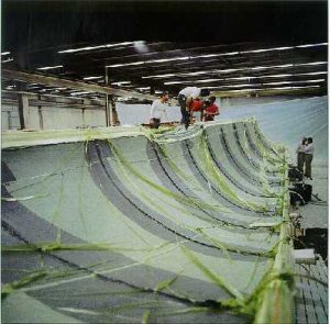 Resin Transfer molding (RTM)is a closed mold low-pressure process that allows the fabrication of composites ranging in complexity from simple, low performance to complex, high-performance articles and in size from small to very large. The process is differentiated from other molding processes in that the dry reinforcement and the resin are combined within the mold to form the composite component. The fiber reinforcement, which may be preshaped, is placed into a tool cavity, which is then closed. A tube connects the closed tool cavity with a supply of liquid resin, which is pumped or transferred into the tool to impregnate the reinforcement, which is subsequently cured. Several similar composite fabrication processes fall into the resin transfer molding category, although there are distinct variants.
Process Variants
Vacuum Assisted Resin Injection.
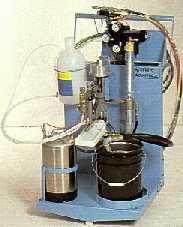 The most common use of the term RTM describes a process typified by the vacuum assisted resin injection (VARI) manufacturing process. A mold is constructed of low cost materials, such as epoxy. Reinforcement is then cut to fit the required geometric pattern and is arranged by hand in the mold. Pieces of reinforcement may be placed in the mold one at a time or preassembled and then placed in the mold as a unit of preform, after which the mold is closed and clamped with bolts or bars. A vacuum can then be applied to the mold to extract the air, and resin is injected at very low pressures, often below atmospheric pressure. Because of the low cost materials used in mold construction, mold pressures must be low, resulting in slow fill times and limited glass contents. The inability of the mold to tolerate elevated temperatures, coupled with its poor heat transfer, restrict the resin chemistry to slow cure times with minimum exotherm to prevent resin degradation or tool damage. Cycle times of this process are measured in hours and days for large, complex parts. The major benefit of the process is the ability to fabricate large, complex structures with maximum part integration at a low cost
Preform molding
A preform of reinforcement is prepared before it is placed in the mold. The preform is usually made by spraying chopped reinforcement onto a perforated screen. A vacuum applied to the rear of the screen holds the reinforcement in place until the binder, which is sprayed along with the reinforcement, has time to cure. After a postcure, the preform becomes an easily handled, three dimensional sheet of reinforcement. Cores and changes in thickness are possible but not generally used ha this process. Preform materials and techniques are further discussed in the section ”Resin Transfer Molding Materials” in this article. Tooling is normally made of steel or zinc alloy, but could also be made of epoxy. The preform is placed in the mold, and a measured quantity of resin is poured or pumped into the open tool. The tool is then closed and compressed to approximately 690 kPa ( 100 psi), causing the resin to flow and ”wet out” the preform. Heated tools are usually used, and the cycle time for large parts of uniform thickness is open 3 min or less. Parts having significant complexity and integration can be made economically using preform molding. Equipment is inexpensive because of the low pressures required. The physical properties of the molded components tend to be very consistent with uniform reinforcement content, even at part edges. Unfortunately, this is at the cost of a relatively high waste factor around the part perimeter. Also, these components do not have the optimum possible level of performance for the amount of reinforcement because of the absence of reinforcement orientation and, to a lesser extent, the presence of a binder.
Structural Reaction Injection Molding Process (SRIM)
This process uses a preform that is placed in the tool before the introduction of the resin system. Tooling can be made from various materials, but is typically a metallic shell in order to facilitate heat transfer. The resin is highly reactive and is contained in two separate holding tanks. Resin from each tank is injected under high pressure into an impingement mixing chamber and then directly into the tool. Although the mixing pressure is high, the overall pressure of the resin, once in the tool, is only about 340 to 690 kPa (50 to 100 psi). The resin flows into the tool and wets out the preform as the curing reaction is occurring. A suitable resin system has a viscosity plateau of 0.1 to 0.5 Pa s (1 to 5 P) for around 20 s followed by a rapid cure, resulting in cycle times of about 1 min. Reinforcement levels used in this process to date tend to be from 5-55 wt%. Resin must enter the tool at fast rate if flow distances are long because of the fast cure times. These high flow rates restrict the choice of reinforcement to those which are resistant to washing (movement caused by resin flow). Because of the rapid onset of resin cure, flow distances are limited in this process, when flow distances exceed 610 mm (24 in).multiple inlet ports are desirable.
High Speed Resin Transfer Molding (HSRTM)
This process encompasses portions of all three at the aforementioned processes.The conceptual process, uses three dimensional preform with foam attachment inserts. Glass content is in 35-60 wt% range and can be a mixture of continuos and random material. Tooling for high production volumes should be made of steels in order to contain moderate molding pressure(690 to 3450 kPa, or 100 to 500 psi) and exhibit good heat transfer characteristics. For limited production, aluminum or zinc tooling would be acceptable. Molding is carried out at elevated temperature to minimize the cure time and expand the number of potential resin system. The preform is placed in the mold and following minimal hand arrangement of the preform, the mold is closed and resin is injected. At higher reinforcement levels, the mold may be left open slightly during resin injection and then closed completely to promote rapid filling in the mold. Cure should be accomplished in the mold such that the final part will require the post cure and will have acceptable dimension stability. For some complex components and components having critical tolerance requirements, a fixtured postcure is required to yield dimensional stability. Cycle times range from 1 min for small components to 8 to 10 longer longer for large, complex structures.
As the degree of complexity, level of performance, and size of composite components increase, labor-intensive processes, such as hand lay up, may increasingly be chosen to make a number of components. Because of its cost, it is unlikely that this technique can be used to make a significant quantity of parts. At the other end of the spectrum are the compression molding and thermoplastic stamping processes. The equipment required to produce parts with these technologies is expensive, thus there is a threshold of number of parts required before these process become financially viable.
The level at which this occurs, when the automotive industry considers the replacement of metal components with composites, depends on the cost of the component being replaced. As the cost of the steel component or system being Replaced increases, the number of parts to be manufactured will decrease. There is, however, an upper limit to the amount of replacement possible using these processes. Because of the limited mechanical properties of materials used with these processes and the inability to make large, integrated structures without assembling multiple small components, these process may only economically replace steel as where the degree of part integration possible is already limited by function. Examples of such areas include grille opening panels, hoods, deck lids, and doors. The high pressures required (7 to 17 MPa, or 1 to 2.5 ksi) also limit the size of the components fabricated by compression molding and thermoplastic stamping.
The RTM process allows placement of preforms of variable thickness containing a variety of fiber types in the mold cavity with minimal subsequent movement of reinforcement during further processing. This contributes to optimum performance at minimum weight. The low pressure required for the process allows the use of less-expensive presses and may slightly reduce the cost of high-volume production tooling, compared to compression molding or thermoplastic stamping. There should, of course, still be the large reduction in tooling expense, when compared to steel components, given a sufficient degree of part integration. The low pressures will also allow much larger structures to be molded. Current compression molding processes are limited by the availability of very large presses. The RTM process allows the incorporation of cores and inserts in the component design. This ability to produce three dimensional structures with deep sections and cores at low pressures allows the fabrication of large, highly integrated structures. In the automotive industry, these are not surface-quality parts but, rather, unseen structures. A superior surface quality currently requires a high pressure process.
Equipment
The presses and resin control equipment required for resin transfer molding are readily available from a number of suppliers. Lower-tonnage presses can be used because of the lower pressures required for RTM, compared to processes such as compression molding. Computer control is desirable to sequence the press closing and resin management for applications in which high speed resin injection and cure are required
Tooling
When required, the presses used in RTM primarily control parallelism of the die set during die opening and closing and also hold the die closed during injection. Because RTM uses lower pressures than does compression molding or thermoplastic stamping, the clamping force required will be considerably lower. Though expensive, injection pressure can be the main factor determining the press size. Basing the size on the average pressure within the tool is a less expensive approach.
Computer simulations are being developed to allow the calculation of the pressure required to fill a component ( 8). One point to consider when sizing a press is the force required to compact the lofted reinforcement preform. For glass preforms in the range of 50 wt%, with a majority of the glass being random material, a closing pressure as high as 690 kPa(100 psi) can be required to close the die.
In the case of a large, highly integrated, composite automotive structure, the cost differential between low cost tooling and standard production steel molding tools may not be significant. There should, however, be large savings in tooling cost over current tooling for fabricating steel structures because of the reduced number of required tools resulting from part consolidation. To realize short cycle times, tooling must be capable of being uniformly heated to about 90 to 150 蚓 (200 to 300 蚌). It must also be rigid enough to compress the lofted reinforcement of the preform as the mold closes, without tool distortion. Hardened shear edges to trim excess reinforcement from the preform in pinch off areas as the mold is closed will reduce post molding finishing time and provide a good seal to contain the resin. Because of the abrasive nature of the reinforcement, and the likelihood of molding a large number of components, tooling surfaces should be chrome plated. All of these requirements limit tool choices for high volume production to materials such as cast aluminum, chemical vapor deposited nickel, and steel. For a production tool, steel will most likely be the best material based on its durability and ability to be easily modified. For low volume and prototype production, however, lower cost epoxy and zinc alloy cast tools are an acceptable alternative. Longer cycle times, reduced dimensional accuracy due to mold compliance, and reduced tool life will likely result from this tooling choice.
Resin transfer Molding Materials
Cost and processability often determine the choice of a resin system. Thermoset materials have been used exclusively to date, but as high performance thermoplastic materials become available in RTM type formulations. they may also be used.
Of the several resin systems that perform adequately in an RTM process, polyester is most often used because of its low cost. Epoxy has been used in both aerospace and consumer products and has been demonstrated to provide high physical properties, but at a premium price. Vinyl ester resin has also been used in a number of RTM products and provides properties between those of polyester and epoxy at a moderate price. Other resin systems, such as the acrylamate resin system family and methylmethacrylate vinyl ester, are newer systems that are proving to be very processible with RTM techniques.
In any resin system, a low viscosity plateau is required, during which the resin can provide constant flow throughout the mold, followed by a fast cure. The resin must not only gel rapidly to be acceptable for rapid RTM cycles, but must provide sufficient Barcol hardness to allow the component to be demolded without distortion. Some resins will yield lower levels of physical properties if cured rapidly, and the processing property relationships of any resin system must be evaluated for each component before it is produced. The speed of resin cure for many available resin systems is already adequate to achieve rapid cycle times. Systems that yield cycle times of 1 min or less, if desired, are available for use with small components. Developments to increase the time available for mold filling and to improve reinforcement wet out after the reactive resin components are mixed together are still needed.
Preforms
Preforms are a critical aspect of the successful implementation of any high volume RTM project. Development of performing techniques and characterization of materials resulting from various preforming techniques should be carried out before finalizing component design. An optimized preform process that gives design and fabrication cost equal consideration must be developed. A structure that is optimized to use the ultimate design capabilities of composite materials, while being highly weight efficient, will likely be expensive and is therefore not appropriate in all applications.
The optimal baseline material for consumer products is typically random E glass. This material is currently being used in many conventional RTM products, including the Lotus, Avanti, and Matra vehicles. The preforming technique most often used with random glass mat is to shape a Sat sheet of this material at the time of molding. In the Lotus process, a sheet of mat is cut and formed to fit in the mold. Overlaps of several inches are made at the end of any layer of material. Foam cores are wrapped with sheets of mat before being placed in the mold. This technique is also used in many other resin-transferred components, ranging from small automotive trim to large waste treatment plant components.
A process in which the flat sheets of glass mat are preshaped before insertion into the mold represents the first level of preforming sophistication. This process uses a flat sheet of Random mat with a small amount (2 to 5%) of thermoplastic binder applied. The binder allows the sheet to retain a shape when it is heated and pressed in a forming die, imparting a gentle, three-dimensional shape to it without cutting and piecing, as in the previous mentioned process. This process, while faster cannot achieve radical three-dimensional shape changes, such as deep draws. It is possible, however to include continuous reinforcement selectively in the preform to improve its physical properties.
The most versatile and widely used preforming technique for creating the preforms with complex shapes is the spray up process. Glass rovings are chopped and sprayed on a rotating screen. A small amount resin is introduced into the stream of chopped glass, and when the glass accumulates on the Screen to the proper weight, the resin is heat-cured causing the preform to retain its shape. The vacuum applied to the back of the screen not only holds the glass on the screen as its accumulates but also helps maintain uniformity. As the holes in the screen become covered by glass, the open areas tend to attract more glass imparting a self-leveling action. This process can be fully automated, and the spray-up of a large preform, such as an automobile floor pan, would take 2 min. This process, while yielding complex shapes, tends to produce resin-transferred components at the low end of the potential physical property spectrum. The binders sprayed with the chopped reinforcement tend to cover and seal off the fiber bundles, resulting in incomplete resin impregnation of the reinforcement.
An approach to preforming that is currently used in the aerospace industry for high performance components is referred to as the engineered fiberform process. When Units of laminates, precut to shape, are stitched together in to three-dimensional structure, they become what is referred to as a fiberform. Fibers used are E-glass, S-glass, carbon, and aramid. The preforming process uses uniaxial fiber rovings that are formed into sheets of varying configurations. Some materials are reinforced solely in the 0 degree direction, while others are reinforced in the 90 degree direction. Fiber rovings can also be oriented at any intermediate angle. These materials not woven, as is cloth, but rather are stitched together with a thread of polyester or aramid. Elimination of the weaving yields improved physical properties and better resin wet-out in the final part.
Performs can be stitched in critical areas reinforcements such as aramid to increase integrity or increase interlaminar shear strength. The fiberform process is similar to assembly of a suit coat or other garment fabric building blocks. Because the process can be carried out on high speed, high volume, fabric processing equipment, the cost of large volumes of fiberforms may be low. Assembly of the fiberform may also be accomplished close to the point of use, allowing shipment of flat precut laminate sheets. Some producers are currently supplying fiberforms to the aerospace industry for fabrication trials and limited production using RTM. Layers of the oriented reinforcement sheets can be stacked and further stitched together into an engineered laminate structure, the structural efficiency of which is high because of exact reinforcement placement and orientation. For some sharply configured parts, laminates can be used as RTM preforms It is unlikely that any optimum preform could made from using one of these processes exclusively Portions of each process could be used, but because the process and the design are interdependent, they must be considered in parallel.
Process Advantages, Limitations, and Applications
The many potential advantages of RTM can be summerized as the capability of rapid manufacture of large, complex high performance structures. The low pressure of the process allows very large components to be manufactured by means of low tonnage presses It also permits the use of foam cores to yield fully three dimensional parts. The ability to preplace the reinforcement where desired, and have it remain in that location, gives increased design flexibility and a subsequent optimized structure. While composites in general offer this advantage over steel, other composite molding processes are either slow and labor intensive or have some degree of movement of the reinforcement, which results in variations in physical properties throughout the finished part. In applications in which composite materials arc competing with steel or other materials on a cost basis. large amount of part integration is required to offset the increased material cost Reduced assembly cost, higher quality, and improved functionality at lower material weights are all possible advantages if a sufficient degree of integration can bc achieved. Resin transfer molding provides the capability to integrate large number of components into one part, and can provide an inexpensive means of obtaining prototype parts at low production volumes. It can also be capable of rapid production of larger volumes when high quality tooling is used. Resin transfer molding is a closed-mold process, which has advantages over open-mold processes, including low vapor emissions. Thc resulting components have both inner and outer surfaces that are dimensionally controlled, thereby requiring a minimum of hand trimming if tooling is properly designed.
Currently, the majority of RTM process limitations stem from the undeveloped nature of the higher speed versions of the process. While resin systems continue to improve, there are still problems with filling large parts with high glass content at low injection pressures. Preform Fabrication far high volume components also currently has limitations. The absence of reinforcement at part edges may be a limitation if ribs and bosses are required in a design. Ribs and bosses must be loaded individually in the tool cavity, and maintaining reinforcement at the part edge and avoiding resin richness at corners of the part can be difficult Scrap losses also may be more costly as component integration increases, and if a large component fails, replacement cost to the consumer can be significant.
There are applications of resin transferred components in the automotive, consumer products and industrial products industries. Ford Motor Company recently completed a concept study in which the entire 90 piece steel front structure of an Escort automobile was replaced by a 2 piece resin transterred front structure. The process used was HSRTM. Although only prototype tooling has been used to date, production cycle times were projected to be in the range of 6 to 9 min. The final structure was stiffer and stronger than the steel structure, at 66% of the original weight.
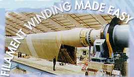 HIGH SPEED PRECISE LAY-DOWN of continuous reinforcement in predescribed patterns is the basis of the filament winding method. It is a process in which continuous resin -impregnated roving or tows are wound over a rotating male mandrel. The mandrel can be cylindrical, round or any shape that does not have reentrant curvature. The reinforcement may be wrapped either in adjacent bands or in repeating bands that are stepped the width of the band and which eventually cover the mandrel surface technique has the capacity to vary the winding tension, wind angle, or resin content in each layer of reinforcement until the desired mess and resin content of the composite are obtained with the required direction of strength.
The most important advantage of filament winding is the cost, which is less than the g cost for most composites. These lower costs are possible in filament winding because a relatively expensive fiber can be combined with an inexpensive resin to old inexpensive composite. Also, cost reductions accrue because of the high speed of fiber lay down, for example, for large parts such as a missile canister, 45 kg/h(100 lb/h) of low angle helical, or 320 kg/h(700 lb/h) of hoop windings
The primary advantages of filament winding are
- The highly repetitive nature of fiber placement (from layer to layer and from part to part)
- The capacity to use continuous fibers over a whole component area (without joints) and to orient fibers easily in load direction Elimination of capital expense of autoclave
- Large structures can be built (larger than any autoclave)
- High fiber volume is obtainable
- Lower cost for large numbers of components
- Relatively low material costs because fiber and resin can be used in their lowest cost form rather than as prepreg.
Thermoset resins used as the binders for the reinforcements can be applied to the dry roving at the time of winding (wet winding) or can be applied previously and gelled to a B stage as prepreg. Also, rovings can be impregnated and rerolled without B staging and either used promptly or refrigerated. The filament wound composite is usually cured at elevated temperatures, without any additional step for compaction. Mandrel removal, trimming, and other finishing operations complete the process.
Materials
Fibers The most widely used fiber for filament winding is fiberglass, which has been marketed in several grades in the United States for more than 40 years. Types of glass fibers useful for filament wound structures, which gives the common designation of the fiber, the nominal tensile strength and tensile modulus of the strands, and the maximum number of filaments per strand. The latter is important in selection of a fiber for filament winding because large numbers of filaments can make handling easier. Fiber density is included in the table so that the rule of mixtures equations involving fiber volume and resin volume can be used to evaluate void volume and theoretical mechanical values. Fiberglass continues to be useful for filament winding because of low cost, dimensional stability, moderate strength and modulus, and ease of handling. Aramid fibers, which were initially useful because of their strength and modulus to-weight ratios (called specific modulus or specific strength), also show great consistency with a low coefficient of variation, enabling high design allowables. Aramid composites have relatively poor shear and compression properties, which are generally not critical for pressure vessels. A new aramid, type 981, has been developed, that has greater tensile strength with the same density (hence improved specific tensile strength).
The largest variety of strengths and moduli can be obtained with graphite fibers, which have recently been improved in terms of modulus, tensile strength, and strain to failure. Surface finish has also been improved, which facilitates handling for filament winding. Increasing tensile modulus usually lowers tensile strength; the intermediate modulus fibers have been the only exception. The amount of graphitization increases with increasing modulus, which results in greater thermal and electrical conductivity. Fiber cost also increases, primarily because there is less demand for the high modulus fibers, and large scale production economics have not yet been imposed. All fibers, except pitch fibers with a modulus of 517 GPa or greater have been filament wound.
Resin Systems The resin system in a filament wound composite serves the same functions as it does in composite structures fabricated by other means, namely:
- Keeping the filaments in the proper position
- Helping to distribute the load
- Protecting the filaments from abrasion (during winding and in the composite)
- Controlling electrical and chemical properties
- Providing the interlaminar shear strength
These are some handling criteria for a wet resin system that are unique to wet filament winding:
- Viscosity should be 2 Pa s or Lower
- Pot life should be as long as possible (preferably more than 6 h)
- Toxicity should be low
One of the important resin properties in the cured structure is adhesive strength to the fiber which is important for most systems, although rocket motors have been filament-wound with released aramid fibers in the hoops direction. Releasing the aramids increases the performance in a biaxial strain field by eleminating transverse loading in the fiber; aramids have very low transverse strength. Another important property is heat resistance, which is critical. A high heat distortion resin system should be chosen only after a thorough study of the operating environment of the filament wound component. Also, fatigue strength, chemical resistance, and moisture resistance of the composite are key selection criteria, but should be evaluated only in relation to the required mechanical properties desired in the operating environment. In addition, high strain to failure capability of the resin system is important to allow transfer of loads s strength or higher modulus fibers.)
Manufacturing Processes A rocket motor case manufactured by filament winding will be used as a basis for addressing typical manufacturing processes and concerns. Key operations involve:
Impregnation Resin and reinforcement are joined in the impregnation process. The types of impregnation processes in common usage are preimpregnated (prepreg) roving (commercial), wet rerolled, and wet winding. Prepregs offer excellent quality control and reproducibility in resin content, uniformity, and band-width control. Many high performance resins can only be impregnated by special processes, such as the hot melt process. Many commercial prepregs can be certified to key government specifications; most use solvents or preservatives added to the resin formulation to extend storage life. These can affect the tack of the roving, making it difficult to remove the roving from the spool during winding. These same solvents can become trapped during B stage and cure. Trapped volatiles promote void incubation, which decreases mechanical strength (particularly shear and compression) in the finished composite. Open, intermediate compaction and heating operations are required to remove these solvents, particularly in thicker walled laminates. With wet rerolled prepreg, a controlled volume of resin is impregnated on a controlled length of fiber reinforcement and then respooled. Quality control can be performed away from the winding operation. Usually no preservatives or solvents are required because the roving is either used immediately or stored in a freezer for future use. This can be a very cost effective method of obtaining preimpregnated roving. Wet impregnation of the fiber can be accomplished by pulling the reinforcement either through a resin bath or directly over a roller that contains a metered volume of resin controlled by a doctor blade. This is a low-cost system that is widely used in commercial applications with polyester resins. The resin content is affected by several parameters: resin viscosity, interface pressure at the mandrel surface, winding tension, the number of layers per inch, and the mandrel diameter.
Mandrel Preparation The tool around which the impregnated roving is wrapped is the mandrel. The principal types of mandrel in common usage in the filament winding industry are water soluble sand mandrels; spider/plaster mandrels for low volume products; segmented, collapsible mandrels for continuous production of pipes; tube mandrels; and unremovable liners, such as load sharing metal liners for pressure vessels. Water soluble sand mandrels are used mainly for rocket motor cases, and the insulator is t almost always reassembled with the mandrel. Wind axis, polar fittings, and other tooling are preassembled, and a water soluble sand solution is cast into the mold around the tooling. Following cure of the sand, the two halves of the mandrel are assembled and bonded. The two insulator halves are spliced using uncured rubber, which co cures with the case. The rough sanded) and cleaned with a solvent. Resin gel coat is applied to serve as an adhesive between the insulator and composite overwrap. The use of a film adhesive in place of the resin gel coat is becoming more common. This provides a controlled adhesive thickness with repeatable properties, but the cost can be prohibitive. Spider/plaster mandrels provide another approach to a high tolerance mandrel surface through use of a plaster sweep over removable or collapsible tooling. The plaster is cured, then overwrapped with Teflon tape or some other separator film. Following cure, the tooling is removed, the plaster is chipped out, and the release tape is removed, leaving the desired inside contour. In some instances, the rubber insulation is laid up and cured directly Waster contour. The process is completed by machining the insulation to the desired contours.
Segmented, collapsible mandrels are specialized and expensive, but the cost is justified for high production applications because of their reusability and the continuous winding process. Surface preparation before winding consists of an application of a mold release and then an ample gel coat to provide a continuous inside surface. The gel coat in this application is designed to provide a flexible barrier to prevent leakage at low strain levels. Tube mandrels are used in many applications involving cylindrical metal mandrels in which the cured composite is pushed (or pulled) off the surface after cure; this requires high quality tooling for trouble free usage. Chrome plating or hardened and polished surfaces assist in easy mandrel removal. A slight taper along the mandrel length is also beneficial.
Unremovable liners are used for metal lined pressure vessels, combining the high strength density advantage of composites with a thin, impermeable metal liner. Using this concept, high pressure low molecular weight gas such as helium or hydrogen can be effectively contained without leakage. The metal liner can be designed to carry a large or small portion of the, internal pressure, but in all cases the liner (which initially serves as the winding mandrel) become vital part of the pressure vessel. The mandrel preparation can vary from an adhesive system, where bonding to the composite is desired, to a released system, where independent movement between the liner and structural composite is desired.
Winding Preparation The manufacturing processes selected for the component are a function of product geometry, weight, and the availability of winding equipment. Most filament winding is still performed using the mechanical gear driven machines which evolved during the late 1950s. However, many of the winding machines now in use are numerically controlled (NC), providing the latitude to wind non optimum shapes where special considerations are required in order to wind the fibers on nongeodesic paths. Analysis techniques have been developed that derive a “slip coefficient” required to prevent fiber slippage from such paths. Because most reinforcements are packaged on rolls, tension can be introduced at the roll. Tensioning devices include magnetic or friction brakes, electronic rewind, and rotating scissor bars. Because the latter two techniques have the capability to rewind, they allow winding of low angle patterns around end domes, since the overtravel past the domes can be taken up. The tensioners are often mounted on reels, either remote to the winder or as a part of the carriage that actually travels with the delivery system. The tensioning devices should have variable but controlled tension levels, easy adjustment of tensions, rewind capability to prevent fiber slacking, and uniform tension regardless of roll size.
Component Winding For rocket motor cases, as for most high quality filament wound components, the manufacturing operation is controlled by detailed documentation. The operator follows this documentations carefully completing patterns, often changing from longitudinal to hoop winding, and verifying quality control. In the prototyping stage of development, the designer’s calculations are checked using pi-tape measurements and thickness measurements at the polar bosses. In production, many quality control verifications can be eliminated, particularly in NC winding operations. Key elements in motor case construction are the skirts at the tangent zones where the domes and cylinders meet. these are attached by various bonding/winding or riveting methods to convey loads through the motor case assembly. The composite portion of the skirt usually consists of hoops and longitudinal fibers interspersed at approximately a 50:50 ratio. These are wound or laid up using temporary skirt tooling, which is removed following cure. The joint between the skirt and the motor case must transfer the combined loading through shear. Often a shear web consisting of rubber or film adhesive is laid up, overwound, and then co cured with the rocket motor case body.
Stage/Cure In the first step in the cure cycle, called B staging, resin viscosity is advanced by means of external heat (lamps or ovens) to the point where cross linking of the epoxide groups is initiated. At this point the resin is still soft to the touch and still exhibits some tack, but will not reflow upon the application of further heat. This operation is performed to allow removal of excess resin before proceeding with cure. This is often done with plastic paddles, wiping off the resin runs periodically until the resin has advanced into the B stage state. In many rocket motor case applications, the domes are B staged first, while the cylinder is temporarily covered with insulation to prevent resin advancement. This allows cocuring of the skirt to the cylinder, and guarantees a “run free” surface for the dome under the skirt tooling.
Fabrication of the composite portion of the assembly is completed by the curing operation. The types of equipment most commonly used are ovens (gas fired or electric), autoclaves, and microwave ovens. Most epoxy resin systems can be cured easily in gas fired ovens without supplemental pressure, using either air or inert gas environments. Recently, vacuum bags and bleeder cloths have been used by some manufacturers to produce more compact, void free laminates. Autoclaves are commonly used with more exotic resins such as bismaleimides and polyimides, where special considerations are required for proper handling of high volatile contents. Autoclaves are state of the art equipment for nonwound components such as skins and panels for aircraft components where the interface pressure between thc continuous fibers and thermally expanding mandrel does not develop during cure. Microwave cure requires a high initial investment but significantly reduces energy costs and cure times. However, special heating supplements such as induction heaters are required at the composite/metal interfaces.
Mandrel Removal The water soluble sand mandrels are the most easily removed; water is added through the wind axis tooling. The sand is washed out and the tooling assemblies removed. Removal is more difficult for mandrels where the tooling is segmented or collapsible. These may require that plaster be chipped out by hand. This operation is laborious and has a high potential for damage to the component.
 Fiber-Reinforced Composites have become an increasingly attractive alternative to metal for many aircraft components. Composites are strong, durable, and damage tolerant. They meet design and certification requirements and offer significant weight advantages. Because they readily adapt to innovative manufacturing techniques, composites also can provide significant cost reduction. The composite materials used in the aircraft industry are generally reinforced fibers or filaments embedded in a resin matrix.
The most common fibers are carbon, aramid, and fiberglass used alone or in hybrid combinations. Aircraft doors, rudder, elevator, vertical tail, horizontal tail, aileron, spoiler, flap, wing box, body, fairing, propeller blades and slats. Current production aircraft components are used extensively on current commercial production aircraft such as Boeing 757, 767 and Airbus A310, which employ about 1350 kgs each, while smaller planes such as the 737-300 use approximately 680 kgs. With the exception of small, detail parts, most composite components for commercial airplanes are of honeycomb sandwich construction. These may be either full-depth designs, such as the 767 outboard aileron or structures built of separate panels such as the 767 rudder. Structures such as fairing, fixed wing, and empennage trailing edge panels are generally fabricated as a sandwich. Face sheets for these panels are made of carbon fiber and carbon/fiberglass hybrid. Such panels most often employ 120 degree C curing systems, and are made either of tape or fabric materials, or with a layer of adhesive for bonding to the honeycomb core.
Phenolic coated fiberglass or honeycomb core is used. The phenolic resin system is used because of its excellent fire-resistant properties, including low flammability and low smoke and toxic gas emissions. The panels are fabricated in a single-stage curing process that provides significant cost advantages in addition to weight savings. Interior parts such as overhead luggage compartments, sidewalls, ceilings, floor galleys, lavatories, partitions, cargo liners, and bulkheads are routinely made of composite components. For relatively flat parts, unidirectional or woven fabrics can be used. For compound contours, stretchable, knitted fabrics are often necessary. The predominant fiber used in interior composites is fiberglass; however, carbon fiber use is increasing as structural applications increase. For example, a filament-wound door spring is employed on the Boeing-767. Using unidirectional carbon fibers in an epoxy matrix, the springs are only one-third as heavy as comparable steel springs and only half the weight of state-of-the-art titanium springs.
The major U.S. aerospace industry users of carbon fiber prepreg materials include McDonnel Douglas, Boeing, General Dynamics, and Northtrop. The largest application by far of composite materials is for military programs, which constitute more than 40% of the aerospace total. About 26% of the structural weight of the U.S.Navy’s AV-8B is carbon fiber reinforced composites. Components include the wing box, forward fuselage, horizontal stabilizer, elevators, rudder and other control surfaces, and over-wing fairings. The wing skins are one-piece tip-to-tip laminae, mechanically fastened to a multispar composite substructure, the design of the horizontal stabilizer is similar to that of the wing. On the F-18 aircraft, carbon fiber reinforced composites make up approximately 10% of the structural weight and more than 50% of the surface area. They are used in the wing skins, the horizontal and vertical tail boxes, the wing and tail control surfaces, the speed brake, the leading edge extension, and various doors. The F-18 composite wing skins are solid laminate; their thickness varies from root to tip, with a minimum thickness of about 2 mm. The B-2 bomber employs a number of composite structural components. The dorsal longeron, weapons bay doors, aft equipment bay doors, and flaps use composites. The structures include laminae, full depth honeycomb reinforced panels, and composite face sheets bonded to aluminum core. The bay doors employ carbon fiber reinforced tape face sheets, aluminum honeycomb reinforced panels, and composite face wheels bonded to aluminum core. Because the doors are in a position that is particularly vulnerable to foreign object damage, an aramid fiber reinforced phenolic outer layer provides penetration resistance.
Use of composite materials in primary structures of major aerospace vehicles was based on the successful use of composites in missiles powered by solid – propellant rocket stages. The space shuttle represents one of the first production applications of a metal matrix composites. It has 242 unidirectional boron-aluminum circular tubes used in the main-frame and rib-truss struts, frame – stabilizing braces, and nose landing gear-brace struts. The major structural components used in space can be grouped into the following categories: Trusses Platforms Pressure vessels and tanks Shells Truss and platform structures usually consist of an assemblage of tubes and flat panels bulkheads.
The tubes are designed to have a very high axial and bending stiffness and low CTE. Mechanical loads are generally low; however, the tube-to-end fitting joint must be designed to withstand thermal stresses caused by thermal cycling and should be stiffness-compatible to minimize the stresses caused by any imposed loads. If these structures are required to operate for long periods of time in low earth orbit, they must be protected from atomic-oxygen attack and degradation of material properties due to radiation. Pressure vessels and tanks are required to contain a wide variety of gases and fluids. Because most composite materials are porous, pressure vessels and tanks made from composites must contain some kind of liner. Therefore, the major design consideration for composite pressure vessels and tanks should be centered around the load-sharing and strain compatibility of the liner and composite under pressure / depressurization cycling, the thermal-strain compatibility of the liner and composite under thermal cycling, the stress-rupture and creep capability of the composite under long-term pressurized loads, and the leak-before-burst capability of the liner and composite systems.
Shell structure can be used in several applications. Like truss structures and pressure vessels, shells must be designed to withstand space environments and to meet the stiffness requirements imposed by the mission. The most critical design consideration for shells is the manner in which the shells are attached to each other, or to adjoining structures. The major structural components of most missile systems are the rocket motor cases, nozzle, skirts, and interstage structures, control surfaces, and guidance and control structural components. The design, material selection, and fabrication process for these components should result in the most cost-effective structure that satisfies all the mission objectives while maintaining all the imposed constraints.
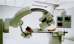 The commercial application of structural composites has an extensive history in the marine, aerospace, and construction industries. Specialized composites also are making significant impacts in the sporting goods industry. In general, these structural composite applications are produced at relatively low volumes and have long process cycles times, compared with high-volume structural material applications. Automotive applications can be categorized as having mainly structural or mainly appearance requirements. Fenders and fascias are primarily appearance parts, with only local strength and stiffness requirements for attachments and oil-canning resistance. Load floors are structural, with only minor appearance needs. Hoods, roofs, and doors, however, contribute in varying degrees to the overall vehicle structure and must provide the same quality appearance as fenders and fascias. Structural requirements can be subdivided into primary and secondary requirements. The primary structure reacts to the major loads such as static and dynamic external loads and to component loads, while the secondary structure supplements the primary one by addressing local requirements such as surface appearance, sealing, and carrying minor components. The secondary structure can act to stabilize the primary structure for an optimized overall design. In the automotive industry, the application of structural composites has been mostly limited to secondary structures and appearance panels. For examples, doors contribute to crashworthiness, but are largely secondary structures. Composites are used in various military applications as well including body armor, armored vehicles and infantry transportation vehicles, bridges etc.
Aerospace and aircraft applications are often considerably different from automotive application in that exterior surfaces are often an integral part of the primary structure of the product. The face that structural composite have been used extensively for both primary and secondary structures is due o low production rates and an emphasis on reduction of weight as opposed to the cost. The typical automotive composite parts include floor pan, rear compartment pan, motor compartment front panel, dash panel, roof panel, rear end panel, quarter inner panel, quarter outer panel, trunk lid interior panel, trunk lid outer panel, front fenders and hood assembly. The Chevrolet X-II hood, introduced in 1980, was the first major flat panel on a GM car. It provided surface finish and design-for-appearance experience for many subsequent applications. The current Corvette uses the design and processing criteria established by the front end panel and X-II applications. All GM General and Astro trucks have three – piece SMC doors that replaced seven-piece steel assemblies and feature modular hardware access. The Fiero program uses the first composite-skinned vehicle operating at high production line rates. Filament wound leaf springs were introduced on high-volume car and van programs.
Although the multitude of composite materials and processes now available can make design process decisions difficult, most major companies have developed material selection and design criteria based on continuous improvement and past experience. This section features these points that must be considered when determining which materials are best suited for automotive body panels. In general, the structural qualities of panels can be categories by stiffness and strength requirements. The stiffness requirements provide the rigidity necessary to resist deflection, oil-canning and buckling, and to ensure the desired vibration response. The strength requirements provide the needed failure resistance under service loading. In addition, certain panels contribute to crash resistance and energy management when a vehicle is tested under safety loading conditions. In the case of body panels the equal stiffness requirement is selected as the only performance constraint. This can be justified for preliminary design evaluation because experience has shown that stiffness requirements are usually the most restrictive. A structural panel can be evaluated for strength after it has been designed for stiffness, and modifications for strength can be added.
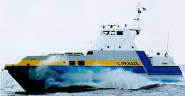 The marine use of fiber-reinforced materials is extensive. Mine warfare vessels, future large ship hulls, sonar domes, submarine structures, submersibles, navigational aids, offshore engineering, hydrofoils, hovercraft, passenger ferries, powerboats, racing yachts, pleasure boats and luxury yachts, composite masts and laminated sailcloth utilize composites in their construction. The primary advantages of using composites in marine applications are Weight reduction and therefore lower purchase procedures and running costs Improved safety due to increased toughness Increased comfort due to the vibration damping properties of the composites used Higher speed (28 knots) The main hull girder is fundamentally a simple single-skin monocoque structure without any longitudinal or transverse reinforcements other that main decks and main bulkheads.
Glass-reinforced plastic tankers, trawlers, and ferries of up to 80 m are currently economically viable. Filament wound ship hulls up to 60 m have also been produced. LeComte Holland BV produces series of simple, versatile, FRP landing craft by using vacuum-assisted injection molding process. The primary resin system used is polyester, along with S- and E-glass, carbon and aramid fibers. The use of composite hulls is found to produce 1.7 knot increase in speed at identical horsepower, fuel consumption dow 20 L.h at full throttle and a two-point decibel reduction sound levels in the boats. Glass-reinforced plastics are also used in sonar domes. These structures are almost constantly immersed in the sea, and are subject to slamming pressures in rough weather.
Submarine structures use GRP structures in the fairwater for limiting excessive wake, vibration, and noise produced by periscopes, antennas, and masts. The use of glass-reinforced plastic for pressure hull and buoyancy structures is also found in submersibles. Submersibles for commercial operations hdow to 457 m have been built using GRP pressure hulls. A third-generation remotely operated vehicle, Solo, has been developed by Slingsby Engineering Limited. Designed for a variety of inspection and maintainence functions in the offshore industry, it carries a comprehensive array of sophisticated equipment and is designed to operate at a depth of 1500 m under a hydrostatic pressure of 15.2 Mpa. Glass fiber woven roving is used in the construction of the pressure hull, chassis and fairings. Unidirectional fabric is used in stressed and jointed areas, and chopped-strand mat is used in sections to be machined.
Navigational Aids: Soft plastic materials including GRP, polyethylene foam/polyurethane elastomer, and syntactic foams are being used for the progressive replacement of exists steel buoys in the North Sea because of increase concern to damage in vessels that serve as navigational aids. Balmoral Glassfiber produces a comprehensive range of buoys and a light tower made of glass-reinforced plastic that can withstand winds to 56 m/s (125 mph). Buoys are also available for a variety of tasks. Anchor mooring buoys applied to the Egyptian offshore oil industry are believed to be the largest ever produced using GRP (4 m in diameter and 15000 kgs) capacity.
Offshore Application : Composite materials also provide a multitude of services in offshore hydrocarbon production, where they usually replace steel because of their lightness, corrosion resistance, and good mechanical performance. It has been proposed that submarine pipelines could be constructed with circumferential carbon fibers for resistant to external pressure and longitudinal glass fibers for lengthwise flexibility. Drilling rises for use at greater water depth are subject to compression and possible failure because the longitudinal resonant period of the disconnected rising is close to that of typical wave periods. The mass reduction on changing from steel to composites materials significantly reduces the dynamic stress and therefore increases either the working depth or the safety f deep-water drilling. It has been reported that 15 m lines manufacture d from carbon and glass fibers have a burst pressure of 168 Mpa. Self-righting, totally enclosed, motor – propelled survival craft and open lifeboats are manufactured in glass-reinforced plastic using fire-retardant resins. The craft range in size from 6.2 m to 8.75 m up to 66 persons capacity. As part of the certification trials, the survival craft must withstand 30m high kerosene flames and temperature of 1150 degree C, which is satisfied adequately by the composites design. A new type of rigid-hull, inflatable, rescue boat has been introduced by LeComte. The deep V-hull is fabricated in one piece with the deck by vacuum-assisted injection molding of Aramid hybrid aramid-glass fabric around a polyurethane foam core. The boat speeds are above 25 knots, and a 25% weight saving is realized when using hybrids in place of glass fiber.
Hovercraft blades of hybrid carbon-glass fiber reinforced plastic have a successful in-service record in hostile environment of seaspray with sand which causes erosion and corrosion. These problems and the noise level can be reduced by lowering the propeller tip speed, but the blade length must be increased to retain the same thrust. The composite blade replaces the 2.7 m SRN6 duralumin blade, consisting of a polyurethane foam core covered with GRP skin. The blade is stiffened with carbon fiber reinforced plastic and a polyurethane strip to protect the leading edge. The spars carry both the centrifugal and bending loads. The textile reinforcement of elastomers is extensively used in the fabrication of the skirts that confine the air cushion of hovercraft. Both the fabric fiber/rubber bond resists fatigue and tearing as a result of flexure or abrasion.
Passenger Ferries Several passenger ferries utilize large amount of composites in their construction. For example, the Norwegian company Brodence Aa recently launched a 184-passenger commuter ferry. The 27-m catamaran has a beam of 9 m and a draft of 1.05 m. Construction is PVC foam cored glass-reinforced polyester built on a timber skeleton mold. The structural laminate used for internal bulkheads is given a final coat of colored resin to provide a practical, cleanable, textured surface without adding finishing weight, thus allowing the vessel to achieve a maximum speed of 33.5 knots.
 Fishing rods, tennis rackets, golf sticks, baseball bats: These are just a few examples of advanced composites applications. Modern high-quality composite rods use a hollow tubular structure to minimize weidght and to optimize the strength and sensitivity of the rod in sport fishing. All such tubular fishing rods are created around a removable metal mandrel, which forms the tapered inner diameter of the finished product. The taper and diameter of this cylindrical cone constitute the starting point of the design. On this inner mandrel are placed the various fibers that provide the strength of the fishing rod and the resin that bonds the fibrous structure together. By altering the mandrel and changing the amount and locations of the fibers used in construction, fishing rods of different characteristics can be made for all segments of the market on a few basic pieces of manufacturing equipment.
Golfing: The major stress on a golf club occurs when the golfer misses the ball and hits the ground. Both the torsional and bending loads applied to golf club shafts, either in mishap or in hitting the ball, must be considered in golf club design. The construction of a golf club is similar that of a fishing rod, however the designer pays more attention to torsional loading, and the requirement of feel or control, has an entirely different meaning. To golfers, the control of the club is tied to a sweetness upon impact plus the ease and reproducibility of directional control of the ball. To combat crushing loads, the manufacturing process begins with a close spiral wrap (to prevent the collapsing-straw effect), followed by a second spiral wrap that places the fibers at a lesser angle relative to the shaft axis. These layers form the effective core that handles torsional and radial impact loads.
Pole Vaulting: as never imposed any particular constraints on the construction or design of the pole. However, there was little change in the design or materials of construction until the advent of fiberglass composites. The poles had been made of bamboo, steel, or wood, but recently fiberglass-resin poles were successfully introduced. The engineering problem involves the design of a very light, highly efficient tubular spring that is loaded by impact when the running vaulter places one end of the pole in the planting box beneath the vertical bars of the vault. The kinetic energy of running must be converted into a rotation energy that is sufficient to carry the vaulter to a vertical position and over the measuring rod. The strength of a composite fiberglass poles per unit weight is greater than earlier materials. Carbon and glass fibers are used to improve the stiffness.
Tennis Rackets: Graphite tennis rackets are becoming increasingly popular over recent years. They provide light weight yet high stiffness advantages.
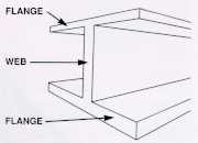 A structural sandwich is a special form of a laminated composite comprising a combination of different materials that are bonded to each other so as to utilize the properties of each separate component to the structural advantage of the whole assembly. Typically a sandwich composite consists of three main parts; two thin, stiff and strong faces separated by a thick, light and weaker core. The faces are adhesively bonded to the core to obtain a load transfer between the components.
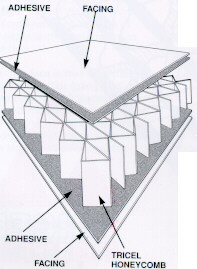
The design principle of a sandwich composite is based on an I-beam, which is an efficient structural shape because as much as possible of the material is placed in the flanges situated farthest from the center of bending or neutral axis. Only enough material is left in the connecting web to make the flanges act in concert and to resist shear and buckling loads. In a sandwich, the faces take the place of the flanges and the core takes the place of the web. The difference is that the core of a sandwich is of a different material from the faces and it is spread out as a continuous support for the faces rather than concentrated in narrow web. The faces act together to form an efficient stress couple or resisting moment counteracting the external bending moment. The core resists shear and stabilize the faces against buckling or wrinkling. The bond between the faces and the core must be strong enough to resist the shear and tensile stresses set up between them. The adhesive that bonds the faces to the core is of critical importance.
The primary advantage of a sandwich composite is very high stiffness-to-weight and high bending strength-to-weight ratio. The sandwich enhances the flexural rigidity of the structure without adding substantial weight. Sandwich structures have in several applications shown to have fatigue strength, acoustical insulation and additional thermal insulation. The absorption of mechanical energy can in some deformation modes be multiplied compared with monocoque structures due to an imposed shorter modes of buckling waves. The use of cellular cores obviates the need to provide additional thermal insulation, ensuring low structural weight, since most cellular cores have a low thermal conductivity.
Applications of Sandwich Structures
GRP terrain vehicles use sandwich in parts of the structure to obtain higher stiffness and strength and integrated thermal insulation. Low structural weight is a feature of the vehicle in order to be able to operate in deep snow conditions. By reducing the structural structure, the pay-load can be increased. A similar application to the truck structure is the sandwich container which possess low weight with high thermal insulation for the transportation of cold goods, e.g. fruit or other types of food. Sandwich structures are also used for transportation applications, including cars, subway cars and trains with an aim of reducing weight, emissions, and to integrate details for reduced manufacturing costs, acoustical and thermal insulation. Sandwich design is also included in flooring, interior and exterior panels.
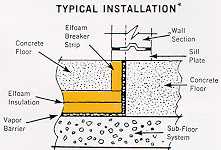
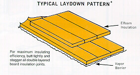
There is a variety of pleasure boats and ships made in sandwich design. In pleasure boats, decks and hull are commonly made in a sandwich design. Even larger ships utilize GRP sandwich design to combine high energy absorption capability and low structural weight. In civil engineering applications, sandwich panels have been used for a long time in low weight and thermal insulation.
In aerospace, sandwich construction has been used for a long time and applications include wings, doors, control surfaces, radomes, tailplanes, stabilizers, space structures, antennas and solar panels for both military and civil aircraft.
Materials and Material Properties
Almost any structural materials which is available in the form of thin sheet may be used to form the faces of a sandwich panel. The properties of primary interest for the faces are :
- High stiffness giving high flexural rigidity
- High tensile and compressive strength
- Impact Resistance
- Surface finish
- Environmental resistance
- Wear resistance
The commonly used face materials can be divided into two main groups: metallic and non-metallic materials. The former group contains steel, stainless steel and aluminum alloys. There is a vast variety of alloys with different strength properties whereas the stiffness variation is very limited. The larger of the two groups in the latter; including materials such as plywood, cement, veneer, reinforced plastic and fibre composites.
Cores
The cores used in load carrying sandwich constructions can be divided into four main groups; corrugated, honeycomb, balsa wood and foams. First of all the core should possess low density in order to add as little as possible to the total weight of the sandwich construction. The core is mainly subjected to shear and the core shear strains produce global deformations and core shear stresses. Thus, a core must be chosen that won’t fail under the applied transverse load and which a shear modulus high enough to give the required shear stiffness. The critical wrinkling load depends both on the Young’s modulus and shear modulus of the core. Other functions of the sandwich such as thermal and acoustical insulation depends mainly in the core material and its thickness. The properties of primary interest for the core are density, shear modulus, shear strength, stiffness perpendicular to the faces, thermal and acoustical insulation.
The most commonly used honeycombs are made of aluminum or impregnated glass or aramid fibre mats, such as Nomex. Due to the manufacturing methods involved most honeycombs have not only different out-of-plane properties but also in-plane properties are different from each other. This is easily seen as both the corrugation and the expansion process produces double cell wall in one direction and single walls in the other. Over-expanded cells also create additional anisotropy. There are three principal directions to which material properties of most honeycombs are referred; the width (W), the length (L), and the transverse (T) directions. Honeycombs have excellent properties, very high stiffness perpendicular to the faces and the highest shear stiffness and strength-two-weight ratios of all available core materials. The main drawbacks are high cost and difficult handling during layup of sandwich element and that they may not be used with wet lay-up manufacturing.
Cellular foams
The relatively recent development of high density and high quality cellular foams has had a major impact on the use of the sandwich concept. Cellular foams do not offer the same high stiffness and strength-to-weight ratios as honeycombs. Firstly cellular foams are in general less expensive than honeycombs but more importantly, they are a solid on a macroscopic level making the manufacturing of sandwich elements much easier; the foam surface is easy to bond to, surface preparation and shaping is simple and connections of core blocks are easily performed by adhesive bonding. In addition, the foam offers high thermal insulation, acoustical damping, and the closed cell structure of most foams ensures that the structure will become buoyant and thus water penetration is of little problem. Variety of foams are used:
Polyurethane Foam
The urethane polymer is formed through the reaction between isocyanate and polyol, and tri-chlor-flour-methane or carbondioxide which is used as a blowing agent and is vaporized by the heat released by the exothermic reaction. PUR foams are produced in many variations from soft foam with more or less open cells to rigid types with predominantly closed cells and in densities of 30 to 500 kg/m3.
Polystyrene Foam
This is produced either by expansion or by extrusion in closed molds. In both cases, the plastic is mixed with the blowing agent which then expands at elevated temperature. A major obstacle was that CFC was used as a blowing agent, but recently PS foams have been expanded without use of environmentally dangerous CFC-gases. PS has closed cells and is available in densities of 15 to 300 kg/m3. PS foam has quite good mechanical and thermal insulation properties, and it is cheap. A drawback is its sensitivity to solvents, particularly styrene, and hence ester-based matrices cannot be used as adhesives but rather epoxy or polyurethane.
Polyvinylchloride Foam (PVC)
PVC exists in two different forms, one purely thermoplastic also called linear PVC foam, and one cross-linked iso-cyanate modified type. The linear PVC has high ductility, quite good mechanical properties but softens at elevated temperature. The cross-linked PVC is more rigid, has higher strength and stiffness, is less heat sensitive, but more brittle. Still, even the cross-linked PVC has an ultimate elongation of about 10% in tension which is much higher than the PUR foam. PVC foam is available in finite size blocks of densities from 30 to 400 kg/m3.
Polymethacrylimide Foam (PMI)
Acrylimide cellular plastics are made from expanded imide modified polycryates. The mechanical properties are very good, perhaps the best of all commercially available cellular foam. PMI is fairly brittle with an ultimate elongation of approximately 3& in tension. The main advantage is the temperature resistance making it possible to use PMI foam in conjunction with epoxy prepregs in autoclave manufacturing in up to 180 degree environment. The cell structure is very fine with closed cells and the density ranges from 30 to 300 kg/m3. The thermal conductivity varies with temperature. For the PMI foam it varies from approximately 0.015 W/m0C at -160 degree C to +140 degree C for the PVC foam.
Adhesives and their Properties
There exists a variety of adhesives for special purpose bonding. The adhesive has to provide mechanical requirements of the structure of providing a good bond between the materials components in the environment that the structure is to work, and considerations like fatigue, heat resistance, strength, aging and creep are of primary interest. The various adhesives that are used are:
Epoxy Resins
These are low temperature curing resins, normally between 20 to 90 degree C, but some formulations are made for high temperature curing (130 to 220 degree C). They have the advantage of being used without solvents and curing without creating volatile by-products and have thus a low volume shrinkage. The absence of solvents makes epoxies usable with almost every type of core material. Epoxy is available as paste, films, powder, or as solid adhesives. The typical shear strength of epoxy is about 20-25 MPa.
Modified Epoxies
Toughened epoxies are similar as common epoxies but mixed with synthetic rubber, like polysulfide elastomers, which greatly improve the peel resistance. The greater the portion of elastomers, the greater the ductility but the creep tendencies increase correspondingly as well and the heat resistance decreases. Other modifications are the inclusion of Nylon to improve filleting and control flow.
Phenolics
Phenolic adhesives have an excellent strength, high temperature mechanical properties and durability. The main drawbacks are that they give off some water when curing making venting essential. The viscosity is also quite high and adhesive films must thus be used. These characteristics have limited the use of phenolics to mainly the process of making honeycombs, where venting is no obstacle and a high temperature bond is required. The out-gassing makes phenolics unsuitable for use in bonding sandwich constructions, apart from applications where venting is possible.
Polyurethanes
PUR adhesives are probably the most widely used for bonding sandwich elements. This is since they provide excellent adhesion to most materials. They can be used as past or liquid in a wide range of viscosities, may have long or short cure times and can be made fire-retardant and water resistant. PUR adhesives contain virtually no solvents and are thus environmentally friendly and the least toxic of all the resins.
Urethane Acrylates
Urethane acrylate is a resin which is compatible with polyesters and vinylesters. In fact, acrylates are so compatible, that they can be incorporated, in e.g. a wet polyester laminate. Urethane acrylates are very tough, and exhibit almost no curing volume shrinkage. A way to increase the face-to-core bond in foam core GRP sandwich-structures is to use urethane acrylate resin for the first reinforcing layer, that is closes to the core. The rest of the laminate can then be laminated wet, using for example polyester resin on top of acrylate layer and still provide a perfect interlaminar bond.
Polyester and Vinylester Resins
Polyersters and vinylesters are the most commonly used matrix materials for reinforced plastic composites outside the aerospace industry. Prefabricated laminates can be bonded to e.g. foam or balsa cores using the same resin as in the laminate. usually, the laminate is built-in directly onto the core and hence the first layer of the laminate is laid wet onto the core and bonds directly to it. It is essential in this procedure to fill all surface cells otherwise leaving dry areas on the bond line. A problem with these resins are their curing volume shrinkage creating sometimes very high interface shear stress. A way of decreasing the effect of shrinkage is to prime the core surface by applying a thin layer of resin to which only fills the surface cells, and which is allowed to cure before the rest of the laminate is applied.
Manufacturing of Sandwich Composites
Popular as wet lay-up is, it is at best limited to moderately loaded structures due to the materials used, the cross-linking conditions employed, and the manner in which the impregnation is accomplished. Both single-skin laminates and sandwich structures for more advanced structures, e.g. for competition yachts and in aerospace applications, tend to be laid up using prepregs. The use of prepregs ensures that the reinforcement is well impregnated and resins used in prepregs also tend to have better properties than the ones available for wet lay-up.
Manufacturing of sandwich components with faces made from prepregs may be accomplished in two overall manners. Under certain conditions, the laminate may be laid directly onto the core in a fashion similar to that used in wet hand lay-up. Alternatively, previous manufactured single-skin laminates may be adhesively bonded to the core in a separate process. To manufacture a single-skin laminate from pregpregs, a one-sided mold is first treated with a mold-release agent, whereupon pregpreg sheets are placed one at a time on top of one another, carefully ensuring that no voids or other contaminants are entrapped and that the sheets are thoroughly tacked to each other. Lay-up of pregpregs is most often performed manually buy may be automated. Automated tape lay-up combining the cutting, lay-up and compaction processes is becoming an accepted process in the aerospace industry to manufacture unidirectional reinforced flat or nearly flat components.
Since almost all resins used in prepregs require controlled temperature and pressure to varying degrees to achieve intended properties, cross-linking usually occurs under a vacuum bag and with heat applied; in high-performance applications autoclaves are used. To prepare the laid-up pregpreg stack for cross-linking, it is covered with a perforated separator, a bleeder ply, a second separator, a barrier, a breather ply, and a vacuum bag. The separator ensures that the part can be released, while the bleeder ply absorbs excess resin squeezed out of the pregpreg stack. the barrier prevents the resin from diffusing into the breather, which ensures that the vacuum pressure of the bag is evenly applied. In several types of applications, molds are complemented with caul-plates which may be elastomeric or rigid, normally of metal. Elastomeric caul plates may be added on top o the pregpreg stack to improve the surface finish of the part by ensuring more even pressure. Cast or molded elastic caul plates may also be used to eliminate bridging over concave areas through application of localized pressure. Rigid caul plates are used to allow precise geometrical control at edges, holes, flanges, etc. by not allowing resin bleeding and thus tapering of the part. After the vacuum-bag assembly is completed, the consolidation process starts with evacuation of the bag; vacuum may or may not be maintained throughout the molding operation. Pressure is then applied and the temperature gradually is increased to the specified resin cross-linking temperature, which is maintained for significant amount of time. After cross-linking has been completed, vacuum and pressure are released and the temperature gradually lowered.
In general process sequence for pregpregs involves:
- apply release agent to mold
- arrange vacuum bag assembly on mold place in autoclave
- apply vacuum apply specified pressure and release vacuum
- increase temperature to specified temperature at specified rate
- maintain temperature and pressure for specified time cool at specified rate.
It is often possible to lay up pregpregs directly onto the core and cross-link the face laminate already in place in a process similar to that common in wet lay-up. In aerospace applications, both directly lay-up onto the core and separate face manufacture with subsequent bonding are used. Prepreg lay-up directly onto the core is of increasing interest also in the ship building to improve properties. Also with prepreg layup, balsa and foam core may need to be primed and/or a separate adhesive film added to achieve sufficient face-core bonding. The prepreg lay-up method requires medium capital investments, high if autoclave is used uses resins that require increased temperature, vacuum, and often externally applied pressure to cross-link as intended and that are fairly intolerant to variations in processing conditions is labor intensive is suitable for short production series suitable for structures of any size. Sandwich composites manufactured through prepreg lay-up are characterized by good to excellent mechanical properties low void contents in the laminates faces consistent laminate quality no well-controlled exterior surface if both laminates are laid-up directly onto the core.
This is simple manufacturing operation, independent of face and core materials. Adhesive layers are interleaved between the faces and the core and the whole stack is subjected to increased temperature and pressure as required by the adhesive resin, whereupon the sandwich is cooled. For high-performance applications the bonding process likely takes place using a vacuum bag and an autoclave, whereas for less demanding application it may be sufficient use a vacuum bag and/or weights or a hydraulic press. Since, there should be little or no resin bleeding if the bonding is correctly performed, the vacuum-bagging arrangement is simplified when compared to laminae manufacture. It is normally necessary to prepare the surfaces to be bonded in order to achieve a good enough bond. Unless already done, foam cores are typically sintered and all loose particles removes, they may also be primed. Laminates intended for bonding are often manufactured with a peek ply, which is removed right before bonding to leave a clean and somewhat rugged surface. The surface still should be abraded to ensure proper adhesion. The typical processing sequence for bonding of composite laminates to a honeycomb core using an epoxy adhesive is remove peel plies, abrade surfaces, and wash with solvent apply adhesive film onto faces and place on core arrange vacuum bag assembly on mold place in autoclave and apply vacuum apply specified pressure and release vacuum increase temperature to specified temperature at specified rate maintain temperature and pressure for a specified period of time cool at specified rate. Face materials used may be composite laminates manufactured through prepreg lay-up or any other composites manufacturing technique capable of producing the required face geometry, or sheet metal. In advanced applications, the faces tend to be fibre-reinforced epoxies and the core Nomex or aluminum honeycomb or high-performance and high-temperature-tolerant expanded foams, e.g, PMI or PEI. Metal-faced sandwich structures typically have foam cores, such as PUR and PVC.
The adhesive is used in film or liquid form depending on application and is usually epoxy or PUR. While thermoset adhesives dominate, thermoplastic adhesives are used as well. Adhesive bonding requires small to medium capital investments, high if autoclave is used typically uses adhesive resins that require increased temperature and externally applied pressure to achieve intended properties labor intensive suitable for short production series is suitable for small to medium-sized structures. Sandwich components manufactures through adhesive bonding are characterized by good to excellent mechanical properties well-controlled surfaces (assuming the faces have at least one good surface)potentially having partially failed bonds in curved sections due to geometric mismatch between performance of face and core.
Several related liquid molding processes are used to manufacture sandwich components. They all have in common that the reinforcement is first placed in the mold whereupon the liquid resin is infused into the reinforcement fabric through the difference in pressure.
The liquid molding processes used include:
- Resin Transfer Molding (RTM)
- Structural Reaction Injection Molding (SRIM)
- Vacuum-Injection Molding
Liquid molding has received much interest in recent years due to its capability of producing geometrically complex structures in an economical fashion, without creating an unhealthy work environment since the processes are closed molds. Especially, RTM is becoming increasingly popular in the automobile industry to manufacture components for vehicles produces in short series. The reinforcement in the form of fabrics, and mats or preforms, is placed in the mold together with the core, normally by hand. However, not only cores, but also inserts and fasteners are easily integrated into the reinforcement of the core before impregnation. After the mold is close, the resin is introduced into the mold to impregnate the reinforcement under pressure and/or vacuum. The resin is often heated to lower the viscosity and thus facilitate impregnation. The resin infusion is stopped when the resin font has reached all the ventilation holes in the mold and the resin starts to leak out. the resins used may cross-link at ambient temperature or, alternatively, the mold may be heated. The cross-linking reaction should not begin until the mold is nearly filled, as gelation of the resin will prevent it from impregnating the reinforcement completely, thus creating dry spots and voids. The processes of RTM, SRIM, and vacuum-injection molding are distinguished from one another primarily by the type of resins, molds, and impregnation techniques. In vacuum-injection molding, conventional preformulated resins, similar to those used in the wet lay-up processes, are used. In contrast, SRIM employs highly reactive resins that are mixed right before injection.
Although the resins used in RTM also are similar to those used in vacuum-injection molding, they may either be preformulated or mixed right before injection. In RTM and SRIM rigid, matched molds are used, whereas vacuum-injection molding employs a one-sided mold, often a marginally modified version of wet lay-up mold, covered by a vacuum bag. The RTM and SRIM the resin is injected into the mold under pressure, in RTM sometimes assisted by drawing vacuum at the ventilation ports, while in vacuum-injection molding the sole force driving the impregnation is vacuum drawn from the bag. The difference in resin reactivity between RTM and vacuum-injection molding on the one hand and SRIM on the other translate into two major difference; with the former the mold fill times range from a few minutes to a few hours; in the latter case enabling filling of large parts before the increasing resin viscosity prohibits further impregnation. In contrast, the fill times in SRIM are usually less than a minute due to the much higher resin reactivity, meaning that only smaller parts than with the other two processes are manufacturable. On the other hand, the cross-linking times are in the range of a few minutes to a few hours for RTM and a few hours with vacuum-assisted molding, whilst in SRIM parts can be demolded in a matter of a few minutes. the higher injection rtes of SRIM increase the potential problem of so-called fiber washout, which is when the reinforcement is moved by the advancing resin front. The manufacture of large, complex parts with high fibre volume fractions thus it is more difficult with SRIM than with RTM. In SRIM, the two-component resin is mixed right before injection in an impingement-mixing nozzle using dedicated pumps. In RTM injection may be achieved with a dedicated pump or a simple pressure pot, which is a closed vessel containing the resin; in the latter case the resin is forced out of the pot through injection of pressurized air. With dedicated pumps the resin is mixed right before injection also in RTM. In all three processes multiple inlet pots may be necessary for large components. An alternative way to facilitated complete wettest of large components, especially in RTM, is to inject the resin into a channel running around the entire exterior of the part, allowing the resin to impregnate the reinforcement, from all sides concurrently. Vacuum is drawn or air allowed to escape from the center for the part in one or more locations, so the impregnation occurs from the perimeter and into the center of the part.
From an economical perspective, a continuous manufacturing process naturally is preferable. A suitable way to manufacture continuous sandwich panels is using a double-belt press. It is possible to heat and cool the material while at the same time subjecting it to a specified pressure profile, thus making it a potentially useful device to impregnate and/or laminate composites. When using a double-belt press to manufacture sandwich components, the face sheets are likely coiled up in very long lengths. Two rolls of face sheets are first uncoiled and guided in between the belts of the press. The core is then, in any of a number of fashions, inserted between the face sheets, possibly together with adhesive layers. The faces and the core are then bonded to one another through concurrent application of heat and pressure, whereupon the sandwich is cooled under pressure to consolidate it. Face materials may be sheet metal, unreinforced polymers, and composite laminates or prepregs. To obtain a truly continuous core it may prove convenient to in-situ foam in between the foam through injection and subsequent expansion. An alternative way is to sandwich a thermoplastic polymer film containing a foaming agent between the faces; as soon as the double-belt press melts the polymer film, the foaming agent is free to expand, thus filling the gap between the faces with a foam. It is naturally possible to insert discrete blocks of wood or prefoamed core between the faces, although this procedure brings on concerns of core-core disbonds.
This process is similar to compression molding of single-skin laminates. When using thermoplastic-based faces, e.g, GMT, the material I sheathed in an oven to a temperature exceeding the softening point of the matrix and thereafter placed in a cooled mold with the core sandwiched in-between. The mold closes very fast and the material is forced to conform to the mold before it consolidates, whereupon the component is ejected. Rapid closing is essential to achieve high surface finish. The choice of core material is important to ensure that it has a compression strength adequate to withstand the molding pressure (between 0.2 to 4 MPa) which is important for dimensional stability and surface finish. Also essential is good bonding of the faces to the core. Thermoformability is advantageous, especially for complex-shaped parts; a thermoplastic foam core then may be appropriate since it easily may be reshaped and compacted. Improved bonding between faces and core and improved dimensional tolerance ma be obtained if the thermoformable core is lightly over-dimensioned since the increased pressure caused by core compaction may reduce surface irregularities. The use of thermoplastic cores may further enhance bonding since heating of the face sheets will cause the core surface to melt.
For filament winding of sandwich components the inner face would likely be wound first and the winding stopped to apply a flexible or prefoamed core onto the inner face. The winding would then resume to apply the outer face. A particularly interesting application of filament wound sandwich structures is the self-supporting inner body of a railway passenger-car. the body is wound in three sections. The body sections are mounted through the roof and slid in to position whereupon the roof section is put in place. The interior of the car is either integrated in the wound structure or preassembled.
This is one of the oldest but still one of the most commonly used methods to manufacture sandwich components with composite faces. This method is very flexible yet labor-intensive and thus best suited for short production series of especially large structures. The wet-layup may performed either by hand lay-up or spray-up. The process uses a single-sided mold, male or female, which is treated with the mold release agent. Normally, a neat resin layer, a gel coat, is deposited directly onto the mold which is allowed to gel before the lamination starts. The gel-coat resin usually is of high -quality and has good environmental resistance, thus allowing the use of a lower-quality, cheaper resin within the actual laminate. The gel-coat also produces, a smooth cosmetically appealing surface that hides the reinforcement structure, which otherwise may be visible on the composite surface.
In case of vacuum assisted wet layup the core is placed on top of the laminated but not cross-linked laminate whereupon the vacuum is applied and the laminate is cross-linked. the “top” laminate is then laminated directly onto the core and vacuum preferentially drawn to improve compaction. Alternatively the core and the top laminate may be applied concurrently before applying vacuum. Rolling on top of the vacuum bags is common in order to work out voids and remove excess resin.
The wet lay-up methods
- Require small capital investments
- Typically use resins that cross-link at room temperature with little or not applied pressure and that are tolerant to variations in processing temperature
- use simple tooling due to modest cross-linking requirements
- are labor intensive
- are cost – effective for short production series and prototype production
- are suitable for any size structures, notably very large
- bring on work health concerns due to the active chemistry of the resin.
Applications of wet lay-up methods include:
- motor and sailing yachts
- mine-sweepers and high-speed passenger ships
- refrigerated truck and railroad containers
- storage tanks
Mine-sweepers, or mine-counter-measure vessels (MCMV), longer than 50 meters, wider than 10 meters and with displacements up to 400 metric tons have been built. In this application, composite materials and wet hand lay-up offer substantial advantages; the non-magnetic material is highly relevant so as not to risk detonating magnetically sensitive mines; the foam core sandwich structure is damage tolerant to under-water detonations.
Similarly, surface-effect ships (SES) are capable of transporting up to four hundred passengers at speeds over 50 knots. The SES is a catamaran with curtains between the two keels in bow and stern allowing an air cushion to be maintained between the keels; the air cushion lifts the hull partly out of the water to reduce drag, thus allowing high speeds to be reached. The largest composite sandwich SES built measures approximately 40 by 15 meters.
The main difference between hand laid-up and sprayed-up composites are due to the differences in labor costs and mechanical properties. The lower labor costs of spray-up implies that longer series are economically feasible and the inferior mechanical properties achieved mean that commodity-type products are more common. Sprayed-up sandwich components include small pleasure boats and storage containers and tanks.